
Install Instructions


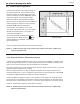


Table Of Contents
- Cover
- Table of Contents
- SECTION 1 Product Accessories
- SECTION 2 Product Characteristics
- SECTION 3 Safety Regulations
- SECTION 4 Installation
- 4.1 Location and Clearances
- 4.2 Wall Mount Bracket
- 4.3 Combustion Air
- 4.4 Venting, Exhaust
- 4.5 General Location Guideline
- 4.6 Locations for Vent Pipe Terminator
- 4.7 Air Supply and Vent Connections
- 4.8 Vent / Air Pipe Termination
- 4.9 Gas Supply and Piping
- 4.10 Gas Supply Pressure
- 4.11 Gas Setup and Adjustment
- 4.12 High Altitude Installations. 2,000’ to 10,000’
- 4.13 Natural Gas to Propane Conversion
- 4.14 Plumbing Guidelines
- 4.14 Plumbing Guidelines
- 4.15 Pressure Relief Valve
- 4.16 Disposal of Condensate
- 4.17 Electrical Wiring Connections
- 4.18 DIP Switches
- 4.19 Control Board, Electrical Diagram
- 4.20 Ladder Diagram
- 4.21 Electrical Connections
- SECTION 5 Control Display and Operation
- SECTION 6 Error Codes
- SECTION 7 Trouble Shooting
- SECTION 8 Maintenance
- SECTION 9 Installation Check
- SECTION 10 Parts
- Notes:

The FT Series Heating Only, Boiler
Page 65
5.9 Outdoor Reset Adjustment
5.10 External Set Point Temperature Control
Outdoor Reset varies the control setpoint based on
the outdoor temperature. The reset function works
as shown in Figure ‘CH Outdoor Reset’. When the
outdoor air temperature reaches 4:OH “high outdoor
temperature setpoint”, the control point setting is
adjusted to 7:cL “low boiler temperature setpoint”.
When the outdoor air temperature reaches 5:OL “low
outdoor temperature setpoint” the control setpoint is
adjusted to 6:cH “high boiler temperature”.
Default outdoor reset setpoint is 100°F (38°C)
A signal from a building management system may be connected to the appliance to enable remote
control. This signal should be a 0-10 volt DC signal. When this input is enabled, a building control
system can be used to control the set point temperature of the appliance.
The control interprets the 0-10 volt signal as follows; when the signal is between 0 and 1.5 volts, the
appliance will be in standby mode, not ring.
When the signal rises above 1.5 volts, the appliance will ignite. As the signal continues to rise
towards its maximum of 10 volts, the appliance will increase in set point temperature. Adjust 6:cH
and 7:cL to set MIN and MAX boiler water temperatures respectively.
Connect a building management system or other auxiliary control signal to the terminals marked
for this purpose on the appliance terminal block (shown in Piping Diagrams, this manual). Caution
should be used to ensure that the 0-10 VOLT + connection does not become connected to ground.
Connect to terminal strip as outlined 4.17 Electrical Connections.
NOTE: 0 - 10VDC terminals may not be used for both outdoor reset and 0 - 10VDC temp
setpoint simultaneously.
The Outdoor Temperature Mode Icon on the display
will ash if an Outdoor Sensor or 0-10 Volt is not
connected to the appliance.
To check the CH Target Temperature while using
Outdoor Temperature Mode, press the
button
while the appliance is operational and the display
panel is powered on.
Connect to terminal strip as outlined 4.17 Electrical Connections.
NOTE: 0 - 10VDC terminals may not be used for both outdoor reset and 0 - 10VDC temp
setpoint simultaneously.
Outdoor Reset
Operating condition
(warm weather shutdown)