
Install Instructions


LAARS Heating Systems
Page 34
Customer Service and Product Support: 800.900.9276•Fax800.559.1583
Headquarters: 20IndustrialWay,Rochester,NH,USA03867•603.335.6300•Fax603.335.3355
1869 Sismet Road, Mississauga, Ontario, Canada L4W 1W8 • 905.238.0100 • Fax 905.366.0130
www.Laars.com Litho in U.S.A. © Laars Heating Systems 1607 Document 4288C
800.900.9276 • Fax 800.559.1583 (Customer Service, Service Advisors)
20 Industrial Way, Rochester, NH 03867 • 603.335.6300 • Fax 603.335.3355 (Applications Engineering)
1869 Sismet Road, Mississauga, Ontario, Canada L4W 1W8 • 905.238.0100 • Fax 905.366.0130
www.Laars.com
Document 4288C
Mascot FT Wall Combi, Gas Conversion Kit
pg 4 of 4
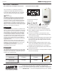
Figure F (Conversion label)
This unit was converted on ____/____/___to _____gas
with kit #____________by______________________
(name and company __________________________
accountable)_________________________________
___________________________________________
Cette unité a été converti ____/____/____ten ______gaz
en utilisant le kit numéro _____ par______________
(nom et société_________________________________
responsable)___________________________________
_____________________________________________
CO
2
value
NaturalGas(NG) PropaneGas(LP)
2˝ VENT 3˝ VENT 2˝ VENT 3˝ VENT
MFTCW (ALL Sizes)
MAX FIRE 8.5 - 10.5% 9.5 - 11%
MIN FIRE 8 - 10% 9 - 10.5 %
NOTE: Installer is required to verify combustion settings as part of the installation process.
CO should not exceed 200 ppm.
H2373800C
Manifold pressure
‘NG’ type combustibility ‘LP’ type combustibility
2"/3" VENT 2"/3" VENT
MFTCW140
MAX FIRE
-0.216
"
WC -0.216
"
WC
MIN FIRE
0.002
"
WC
0.079
"
WC
MFTCW199
MAX FIRE
-0.314
"
WC -0.173
"
WC
MIN FIRE
-0.015
"
WC -0.015
"
WC
adjustments only at LOW Fire), before CO
2
at both are within acceptable levels. Be sure to put the
adjustment port cap screw back onto the valve when done.
22.
Once the CO
2
and manifold pressure measurements for both MIN and MAX Fire are acceptable per
Table C, set DIP switches 6 and 7 to the OFF position for Nominal Fire (normal operation).
23.
Write in the correct Conversion Date and the Technicians Name to the included gas conversion
sticker. See Figure F. Then apply that sticker adjacent to the rating plate.
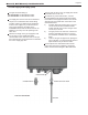
24.
Remove your combustion analyser from the Test Port and be sure to thread the Test Port plug back
into position.
25.
Re-connect outdoor reset if it was disconnected, put the boiler cover back on and assemble/tighten
the 4 screws that hold the cover in place.
Table C
Table D
4.11 Gas Setup and Adjustment
For the Step by step process to measure CO
2
values on the Mascot FT Section 4.13 of this
Installation Manual.
Table 10. CO
2
Values
Table 11. Manifold Pressures
WARNING
Installer is required to verify combustion settings as part of
the installation process.
Standard Factory Setting is for MAX Fire. 9.0%
CO2 @ 0-2,000 ft altitude (Natural Gas).