
Installation Guide


Installation Sequence
IMPORTANT! Several included components will be powered by the control amplifier via 25’ (7.6 m)
cables. Plan the control amplifier location so the cables will reach without being under tension.
For best results, follow the installation sequence below. Detailed instructions are found on the following
pages of this guide.
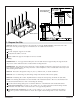
The illustration above shows a typical installation with the preferred user interface and control amplifier
locations. Depending upon your bath the installation will be similar.
Recommended Installation Sequence
Determine the locations for the bath components. Refer to the illustration for preferred locations.
Plan for required access panel locations for servicing the control amplifier, heated surface
components, and other electrical components pre-installed on the bath.
NOTICE: Use wood studs to construct the bath frame. Metal framing may adversely affect the
vibracoustic quality of the product.
Construct the framing for your bath.
Install the rough deck material.
Route the plumbing supply and drain lines for the bath.
Install the bath and drain.
Route the transducer wires to the control amplifier location.
Install an electrical outlet within 24″ (610 mm) of the control amplifier location.
Install an electrical outlet within 24″ (610 mm) of the junction box located on the control board.
If equipped with chromatherapy, route the chromatherapy cable from the bath to the control
amplifier location.
If equipped with heated surface, route the inter-connect cable to the control amplifier location.
Route the user interface cable from the heated surface control located at the user interface location.
Install the control amplifier.
24" (610 mm)
6" (152 mm) Maximum
10"
(254 mm)
User Interface
Control Amplifier
Access
Panel
Transducer
Wires
Chromatherapy Cable
(If Equipped)
Power Supply
Transducer
Heated Surface
Control Board
Access Panel
Heated
Surface
Control
User Interface Cable
Inter-Connect Cable
1297610-2-B 6 Kohler Co.