
Installation Guide


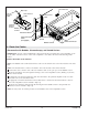


4. Route the Cables
Vibracoustic with Bubbles, Chromatherapy, and Heated Surface
IMPORTANT! Several of the included bath components will be powered by the control amplifier via 25’
(7.6 m) cables. Plan the location of the control amplifier so the cables will reach without being under
tension.
Connect the Cables at the Controls
NOTE: The bubble control and heated surface control are mounted to the control board at the end of the
bath.
NOTE: The heated surface control is mounted to the control board at the end of the bath.
Connect the clear connector end of the user interface cable to the open port on the bubble control.
Route the transducer wires through the framing to the control amplifier location, drilling 1″ (52 mm)
holes where needed.
If equipped, route the chromatherapy cable from the bath to the planned amplifier location. Follow
the same route as the transducer wires.
If equipped, connect the black inter-connect cable that is connected to the heated surface control to
the control amplifier location. Include a drip loop.
Route the user interface cable through the framing from the bubble control to the planned user
interface location. Include a drip loop.
NOTE: If used, route an auxiliary-in cable (not included) to the control amplifier location.
User Interface
Transducer Wires
Control Board
Inter-Connect
Cable
Heated Surface
Control
Chromatherapy
Cable
(If Equipped)
Bubble Control
Inter-
Connect
Cable
User Interface
Cable
Bubble
Control
Drip Loop
Heated
Surface
Control
Kohler Co. 13 1297609-2-B