
Manual


damage the unit.
Protect the unit from direct sunlight.
Unit should be properly grounded. Grounding should comply with local
codes.
Do not connect and disconnect the unit when the circuit is live.
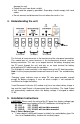
4. Understanding the unit
See Note:
1 2 3 4 5 6 7
To PV Panel To Battery To DC Load
The first pair of screw terminals is the input terminal for solar panel connection.
The second pair of screw terminals is the bi-directional terminal used for
battery connection. This acts as an output terminal for battery charging from
the PV panel through the unit and acts as an input terminal for battery
discharging to DC load through the controller.
The third pair of screw terminals is the output terminal for DC load connection.
Note: Use the jumper provided to connect terminal 6 and 7 for sealed battery
type.
‘Charging’ green indicator turns on when PV solar panel provides enough
energy for battery charging. It turns off when sunlight is not available or
insufficient to charge the battery.
‘Load Disconnect’ indicator (LD models only) turns on when battery charge is
low and the Load Output is disconnected from the battery. The Load Output
will automatically reconnect when the battery voltage is charged to above
12.6V.
5. Installation Instructions
CAUTIONS: Please verify the rating of the PV panel size, battery voltage type
and the total power consumption of the DC load before installing the unit.
SC 1210 12V, 10 ADC
SC 1210LD 12V, 10 ADC with load disconnected
SC 1220LD 12V, 20 ADC with load disconnected
Step 1: Select Battery type
Factory default setting with jumper installed is for sealed battery type. For
the use of flooded battery, remove the installed jumper.