
User Manual


5
Specifications
5-6
- Digital Laser Sensor LV-N10 Series User's Manual -
5-3
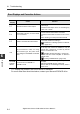
Dimensions
LV-N11
/ N12
(cable type), LV-N10 (0-line type), LV-N11MN (monitor output Type)
*1 This is not installed on the main unit (LV-N11).
*2 Œ3.9 3 pins x Black, White and Pink 0.18 mm
2
on the expansion unit (LV-N12).
Œ3.9 5 pins x Brown, Blue 0.34 mm
2
and Black, Orange, Pink 0.18 mm
2
on the
monitor output type (LV-N11MN).
The cable is not installed on the 0-line type (LV-N10).
LV-N11C
/ N12C
(M8 connector type)
* This is not installed on the main unit (LV-N11C).
Sensor Amplifier
When cover is opened: 108.7 max.
Max. 170°
*1
*2
Black, White and Pink 0.18 mm
2
Cable length: 2m
When amplifier mounting bracket (OP-73880) is used
Bottom surface of
amplifier mounting bracket
Min.
Counterbore: ø6.4 Depth: 2.7
2-ø3.4
2-(4.4×3.4)
Counterbore: ø7.2 Depth: 3.2
ø3.9 5 pins × Brown and Blue 0.34 mm
2
When cover is opened: 108.7 max.
Max. 170°
M8 connector
When amplifier mounting bracket (OP-73880) is used
Counterbore: ø6.4 Depth: 2.7
2-ø3.4
Bottom surface of
amplifier mounting bracket
2-(4.4×3.4)
Counterbore: ø7.2 Depth: 3.2
*