
User guide


3-4 Setting the Tolerance Setting Value
3-12
3
Basic Operations
IL-E
4
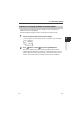
Press S / T button to set the LOW side setting value.
IL-S025/IL-030/IL-S065/IL-065/IL-100
IL-300/IL-600
IL-2000
After setting, press W / X button to return the sub display to the original display as
necessary.
Tolerance tuning
When the target (master workpiece) as a reference is present, the HIGH side setting value
(upper limit) and LOW side setting value (lower limit) can automatically be set with the
master workpiece measurement value as the center value.
1
Press the W / X button several times on the main screen. Then display the
R.V. display screen on the sub display (lower level).
"Sub Display (Lower Level)" (page 3-4)
2
Measure the master workpiece and press the [SET] button.
The judgment value (P.V.) as a reference value for the tolerance setting is imported.
[
set
] and the tolerance setting width are displayed alternately on the sub display (lower level).
Item Setting range
Default value
LOW side setting value -99.999 to 99.999 -5.000
Item Setting range
Default value
LOW side setting value -999.99 to 999.99 -50.00
Item Setting range
Default value
LOW side setting value -9999.9 to 9999.9 -500.0
Reference
As soon as the HIGH side setting value and the LOW side setting value are
entered, the judgment and output begin with the new setting value.
Automatic Setting (When other than step count filter)
Reference
When the tuning result exceeds the setting range, the limit value of the
setting range is considered as the setting value.
Point
The tolerance tuning cannot be performed when the judgment value
(P.V.) is displayed as [-----].
If attempting to perform, [no.uaL] blinks several times on the main
display.
LASER
BANK
0
1
2
3
HI
LO
R.V.
ANALOG
HI SHIFT
ZERO SHIFT
TIMING
LO
ALIGNMENT
HOLD CALC
CHECK
GO
R.V.
[R.V.]
ON