
Datasheet


19
th
JAN 2018 - PRELIMINARY
C4AF
LIFE EXPECTANCY
Life Expectancy
≥ 60.000 hours at U
NAC
and THS=+85°C
Capacitance Drop at End of Life
-5% (typical)
Failure Rate IEC 61709
10 FIT ( ≤10 x 10
-9
/h) at 0.5 X U
NAC
, 40 °C
TEST METHOD
Peak Non-Repetitive Maximum Current
I
PKR
x 1.5
Test Voltage Terminal to Terminal V
TT
2 V
n
for 10 seconds
Test Voltage Terminal to Case V
TC
3k V – 50 Hz for 60 seconds
Endurance Test
500h + 500h @ 1.3 x Rated Voltage @ 85°C
500h + 500h @ 1.3 x Operative Voltage @ 105°C
Damp Heat
IEC 60068-2-78
THB Test 85/85 with Voltage
250 and 310 Vac version
240 Vac 85°C/85% r.h.
500 h: ΔC/C<10% & ΔTg < 3*10-3 at 1 kHz
400 Vac version
335 Vac 85°C/85% r.h.
500 h: ΔC/C<10% & ΔTg < 3*10
-3
at 1 kHz
Change of Temperature
IEC 60068-2-14
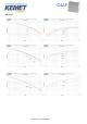
OPERATIVE VOLTAGE DERATING
Voltage (VAC)
Operating Voltage
250
310
400
Rated Voltage @ 85°C (T
HS
)
250
310
400
Operating Voltage @ 105°C (T
HS
)
175
217
280
PART NUMBER CODING
C4
A
F
1
B
W
5330
A
3
N
J
Series
Type
Application
Rated
Voltage
(VAC)
Case
Terminals
Code
Capacitance
Code (pF)
C-spec
Lead
Diameter
(mm)
Size Code: BxHxL (mm)
Tolerance
C4 =
MKP
Power
Capacitors
A = Box,
wire
terminals
F= AC
Filtering
1 = 250
9 = 310
3 = 400
B = Box plastic
case
E = Box plastic
case Extended (
>35x50x57,5)
U = 2 pins
W = 4 pins
Digits 2 – 4
indicate the
first three
digits of the
capacitance
value. First
digit indicates
the number of
zeros to be
added.
A =
Standard
Grade
1 = 0.8
3 = 1.2
W = 11x20x31.5
X = 13x25x31.5
Y = 14x28x31.5
1 = 19x29x31.5
2 = 22x37x31.5
F = 20x40x42
J = 28x37x42
L = 30x45x42
M = 30x45x57.5
N = 35x50x57.5
J = 5%
K = 10%
Digit 6=E
A = 45x56x57.5
B = 45x65x57.5
Reminder
It is not possible to manufacture every part number which could be created from the coding description.
Please refer to the table of standard part numbers below and ask KEMET for other possibilities.