
Datasheet


© KEMET Electronics Corporation • P.O. Box 5928 • Greenville, SC 29606 • 864-963-6300 • www.kemet.com C1078_X7R_FT-CAP_AUTO_SMD • 6/11/2018 13
Surface Mount Multilayer Ceramic Chip Capacitors (SMD MLCCs)
Flexible Termination System (FT-CAP), X7R Dielectric, 6.3 – 250 VDC (Automotive Grade)
Soldering Process
Recommended Soldering Technique:
• Solder wave or solder reow for EIA case sizes 0603, 0805 and 1206
• All other EIA case sizes are limited to solder reow only
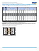
Recommended Reow Soldering Prole:
The KEMET families of surface mount multilayer ceramic capacitors (SMD MLCCs) are compatible with wave (single or dual),
convection, IR or vapor phase reow techniques. Preheating of these components is recommended to avoid extreme thermal
stress. KEMET’s recommended prole conditions for convection and IR reow reect the prole conditions of the IPC/
J-STD-020 standard for moisture sensitivity testing. These devices can safely withstand a maximum of three reow passes
at these conditions.
Storage & Handling
Ceramic chip capacitors should be stored in normal working environments. While the chips themselves are quite robust in
other environments, solderability will be degraded by exposure to high temperatures, high humidity, corrosive atmospheres,
and long term storage. In addition, packaging materials will be degraded by high temperature – reels may soften or warp
and tape peel force may increase. KEMET recommends that maximum storage temperature not exceed 40°C and maximum
storage humidity not exceed 70% relative humidity. Temperature uctuations should be minimized to avoid condensation on
the parts and atmospheres should be free of chlorine and sulfur bearing compounds. For optimized solderability chip stock
should be used promptly, preferably within 1.5 years of receipt.
Prole Feature
Termination Finish
SnPb 100% Matte Sn
Preheat/Soak
Temperature Minimum (T
Smin
)
100°C
150°C
Temperature Maximum (T
Smax
) 150°C 200°C
Time (t
S
) from T
Smin
to T
Smax
60 – 120 seconds
60 – 120 seconds
Ramp-Up Rate (T
L
to T
P
)
3°C/second
maximum
3°C/second
maximum
Liquidous Temperature (T
L
) 183°C 217°C
Time Above Liquidous (t
L
) 60 – 150 seconds 60 – 150 seconds
Peak Temperature (T
P
) 235°C 260°C
Time Within 5°C of Maximum
Peak Temperature (t
P
)
20 seconds
maximum
30 seconds
maximum
Ramp-Down Rate (T
P
to T
L
)
6°C/second
maximum
6°C/second
maximum
Time 25°C to Peak
Temperature
6 minutes
maximum
8 minutes
maximum
Note: All temperatures refer to the center of the package, measured on the
capacitor body surface that is facing up during assembly reow.
Time
Temperature
T
smin
25
T
smax
T
L
T
P
Maximum Ramp Up Rate = 3°C/second
Maximum Ramp Down Rate = 6°C/second
t
P
t
L
t
s
25°C to Peak