
Color Video Camera Instruction


8
2. PARTS NAMES AND FUNCTIONS (Cont’d)
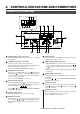
CAMERA HEAD
3
4
2
1
TO CCU LENS
POWER
7
6
5
1
Lens mount
This is where the lens is to be mounted. It fits to the C mount
lens.
Refer to “MOUNTING THE LENS (T14X5.5MD) TO THE
CAMERA HEAD” on page 9.
2
Camera mounting bracket (Accessory)
The camera mounting bracket is not installed on the cam-
era when it is shipped from the factory.
Install it on the top or bottom of the camera according to
your requirements using the two provided camera mount-
ing bracket fixing screws
4
.
Refer to the “HOW TO MOUNT THE CAMERA HEAD” on
page 10.
3
1/4 inch screw hole for camera mounting to a tripod
These are for mounting the camera to a fixed or rotating
table, etc.
4
The provided fixing screws for camera mounting bracket
(two of M2.6 x 6 mm)
Caution:
Make sure to use the provided screws.
Do not use a screw longer than 6 mm because it may cause
a malfunction.
5
[POWER] power supply LED
When the power is supplied to a camera head, this LED
lights.
6
[TO CCU] CCU connector
This is to connect a camera control unit (CCU) with a pro-
vided cable (5 m).
Refer to the “CONNECTING THE CAMERA HEAD AND
CCU” on page 10.
7
[LENS] lens connector
This is to connect the lens to be used.
Refer to the “MOUNTING THE OPTIONAL LENS (T14 X
5.5MD) TO THE CAMERA HEAD” on page 9.
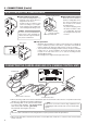
View from the rear of the camera head
(20-pin connector, male)
For the signal names, refer to the “
[TO CAMERA]” on page 6.
1
20
5
19
2
16
10
15
6
11
14
View from the rear of the camera head
(8-pin connector, female)
7
1
68
42
35
Signal
LENS SEL
GND
IRIS CTL/IRIS Y
15V
Pin No.
1
2
3
4
Signal
SERVO SEL
ZOOM CTL
FOCUS CTL
IRIS CTL/IRIS Y
Pin No.
5
6
7
8
29
[FLASH] Flash signal output connector (BNC)
When the FREEZE item is set to the FLASH, a flash signal
is output from this connector according to FREEZE input.
It is recommended to be used when the unit is operated
with a flash.
Refer to the “SYSTEM APPLICATION” on page 11.
Refer to the “FLASH Function” on page 28.
30
[WEN] write enable signal output connector (BNC)
It outputs the write enable signal.
Connect to the image processing unit, etc. .
Refer to the “SLOW SHUT FUNCTION” on page 27.
Refer to the “Random Trigger Function” on page 28
31
[FREEZE] freeze input connector
This is a trigger input signal connector from an external source.
It connects with an external trigger unit such as foot switch, etc.
A negative electrode signal with a pulse width of 20µ sec. to
50µ sec. and a pulse interval of 40 msec. or more should be
input for the trigger signal.
Refer to the “FREEZE SCREEN” on page 21.
CAMERA CONTROL [Rear side] (Cont’d)