This .pdf document is bookmarked Operating Instructions and Parts Manual Drum Sander Models JWDS-1632, JWDS-1836 Model JWDS-1632 shown with optional infeed/outfeed tables JET 427 New Sanford Road LaVergne, Tennessee 37086 Ph.: 800-274-6848 www.jettools.com Part No.
other reproductive harm. (California Health and Safety Code Section 25249.6) 12. Do not operate this machine while tired or under the influence of drugs, alcohol or any medication. 1.0 IMPORTANT SAFETY INSTRUCTIONS 13. Make certain the switch is in the OFF position before connecting the machine to the power supply. WARNING – To reduce risk of injury: 1. Read and understand the entire owner's manual before attempting assembly or operation. 2.
27. Use recommended accessories; accessories may be hazardous. improper 33. Stand out of the path of workpiece when feeding a board. 28. Maintain tools with care. Keep conveyor and abrasives clean for the best and safest performance. Follow instructions for lubricating and changing accessories. 34. Always feed stock against the rotation of drum. 35. Keep hands clear when feeding parts onto the conveyor.
3.0 Table of contents Section Page 1.0 IMPORTANT SAFETY INSTRUCTIONS ....................................................................................................... 2 2.0 About this manual .......................................................................................................................................... 3 3.0 Table of contents ............................................................................................................................................ 4 4.
4.0 Specifications Model number ....................................................................... JWDS-1632 ................................................... JWDS-1836 Stock numbers: Sander with open stand ........................................................ 723520K.........................................................723530K Sander only........................................................................... 723520B.........................................................
Conveyor: Conveyor speed……………………………………infinitely variable within 0 to 10 FPM (0-3 MPM) ............................. Conveyor table dimensions……………………………..17-15/16 x 16-17/32 in. (456 x 420 mm)................................. Conveyor height from floor…………………………………………..31-31/32 in. (812 mm) ........................................... Dust collection: Dust port outside diameter............................................ 4 in. (100mm)................................................. 4 in.
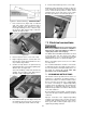
Read and understand the entire contents of this manual before attempting set-up or operation! Failure to comply may cause serious injury. 6.0 Setup and assembly Open boxes and check for shipping damage. Report any damage immediately to your distributor and shipping agent. Do not discard any shipping material until the Drum Sander is assembled and running properly. Figure 6-1: box #1 (main unit) Compare the contents of your boxes with the following parts list to make sure all parts are intact.
Figure 6-3: Assembly 7. 6.3 Assembling stand Level the stand using the leveling feet. Tighten the hex nuts against the leg flange. (Refer to Figure 6-3. If further clarification is needed, consult parts breakdown at back of this manual. 6.4 Mounting sander to stand 1. Assemble legs (F) to outside of Short Rails (D) using carriage bolts (J) and flanged lock nuts (K). Finger tighten only. 1. 2. Assemble Long Rail (E) on inside of legs and on top of Short Rails (D). Finger tighten only.
5. 6. 6.6 Dust collection Position sander atop stand so that the four threaded holes of base align with holes in the stand rails (Figure 6). Dust collection is mandatory for a safe work environment and extended abrasive life. The JWDS-1632/1836 is equipped with a 4-inch dust collection port. Secure a 4-inch dust collection hose to the port with a hose clamp (Figure 6-5), and connect to a high volume dust collector (minimum 400 CFM). Note: Dryer vent hose is not acceptable for this purpose.
6. Release inboard take-up lever to secure strip. All abrasive strips will stretch over time as they are used, and may stretch enough to allow the take-up lever to reach its lowest position so that it cannot maintain tension on the strip. If this occurs, follow the above procedures to reset the take-up lever. Figure 6-7: abrasive trimming – JWDS-1836 ONLY 1. Press fastener lever (Figure 6-8) on outboard (left) end of drum, and insert tapered end of abrasive through slit in fastener, as shown.
use one heavy enough to carry the current your product will draw. An undersized cord will cause a drop in line voltage resulting in loss of power and overheating. Table 1 shows correct size to use depending on cord length and nameplate ampere rating. If in doubt, use the next heavier gauge. The smaller the gauge number, the heavier the cord. If repair or replacement of the electric cord or plug is necessary, do not connect the equipmentgrounding conductor to a live terminal.
one side of conveyor. If it drifts, tighten or loosen take-up screw. Note: Adjust take-up screw only 1/4 turn at a time. Allow time for belt to react to adjustments before proceeding further. Try to avoid over adjustments, as this may affect belt tension. If tension is affected, if may become necessary to use both take-up screws to accomplish tensioning and tracking. 8.3.
6. If drum does not contact gauge equally on both ends of drum, alignment is needed. To align conveyor table with drum: 7. Loosen both table locking screws (B, Figure 83) Loosen both table locks before adjusting drum alignment. 8. 9. Turn knob (C) to raise or lower outboard end of table. Follow directional marks on label (+ raises, - lowers). Figure 8-4: tension adjustment screws Retighten table lock screws (B).
9.2 Switch safety key Do not start drum while in contact with stock. To prevent unauthorized use of sander, turn off main switch and pull out safety key (Figure 9-1). Store key in a safe place. Key must be reinserted to start sander. 3. Without changing drum height, turn on conveyor and run the stock out from under the drum. Start sanding drum and sand stock at that same position. 4. With the drum operating, feed stock under the drum from the infeed side and against the rotation of the drum.
thinnest piece and process all pieces to that same thickness in one session. Be aware that the sander will remove cups and crowns in the workpiece; consider this when measuring and processing stock to the same thickness. If the load on the drum motor increases, the SandSmart control will decrease the conveyor feed rate and will stop the conveyor under extreme conditions.
9.6.7 Stock feeding angle Some pieces, because of their dimensions, will need to be fed into the machine at a 90° angle (perpendicular to drum). However, even a slight offset angle of stock will provide for more effective stock removal. The optimum feeding angle for stock removal is about 60°.
8. Set conveyor on motor side and slide conveyor belt off end of conveyor table. 9. Install new belt along with trackers (see sect. 11.0), and re-install conveyor table. Tension and track the new belt. 4. Pull out brush and inspect. Brush should be replaced if any of the following are discovered: • Brush has worn to about 1/2-inch long. • Signs of crumbling, burning or breaking. • End of brush is rough or pitted. • Abnormal coloration of spring • Broken lead in spring 5.
11.0 Tracker kit 8. Install second tracker opposite the first. Use both trackers unless the second one does not fit in conveyor or unless conveyor belt is damaged. 9. Turn conveyor table right-side up and reposition it onto sander. Re-attach three mounting screws and tighten. Caution: Be careful not to knock tracker(s) out of conveyor table when turning conveyor over. Trackers may break if allowed to fall. Stock No.: PM2244-213 Trackers dramatically reduce tracking adjustments of conveyor belts.
Note: Grits that are too fine can sometimes burnish the wood and leave a glossy surface which will not accept stains evenly. This will vary by type of wood. Oak, for example, is susceptible to burnishing because of its open pores. 12.0 Abrasives The abrasive material you choose will have a substantial effect on the performance of your sander. Variations in paper type, weight, coating and durability all contribute to achieving your desired finish. 12.
13.0 Troubleshooting JWDS-series Drum Sander Symptom Possible Cause Correction * Drum motor won’t start No incoming current. when switch is activated. Safety key missing from switch. Install safety key. Low voltage. Check power line for proper voltage. Open circuit in motor or loose connection. Switch malfunction. Inspect all lead connections on motor for loose or open connections. Replace switch. Drum motor will not start: Short circuit in line cord or plug. fuses blow or circuit breakers trip.
Symptom Sander burns wood. Board slips on conveyor belt. Possible Cause Correction * Abrasive strip is overlapped. Re-wrap abrasive strip. Abrasive is loaded. Clean abrasive. Depth of cut excessive for fine grit. Use coarser grit or reduce depth of cut. Feed rate too slow. Increase feed rate. Abrasive is worn. Replace abrasive. Tension rollers too high. Lower tension rollers. Excessive feed rate. Reduce feed rate. Dirty or worn conveyor belt. Replace conveyor belt. Ripples in sanded A.
14.0 Optional accessories 98-0130 723521 Locking Casters, set of 4 Infeed/Outfeed Tables The following abrasives are available only for model JWDS-1632 (Abrasive strips are 3” wide, cloth backed, aluminum oxide, resin bond, open coat.
15.1.
15.1.2 JWDS-1632/-1836 Head Assembly – Parts List Index No Part No Description Size Qty 1 ................ JWDS1632-101 ......... Dust Hood ................................................................ ...................................... 1 .................. JWDS1836-101 ......... Dust Hood ................................................................ ...................................... 1 2 ................ TS-1503041 .............. Socket Head Cap Screw .....................................
Index No Part No Description Size Qty 54 .............. JWDS1632-154 ......... Motor........................................................................ 1.5HP, 115V, 60Hz ....... 1 .................. JWDS1632-154SC .... Starting Capacitor (not shown) ................................ 300MFD 125VAC .......... 1 .................. JWDS1632-154SCC . Starting Capacitor Cover (not shown)...................... ...................................... 1 .................. JWDS1632-154FC ....
15.2.1 JWDS-1632/-1836 Conveyor Table Assembly – Exploded View 27 2 5 4 6 3 22 9 23 24 11 12 7 8 9 21 17 18 19 15 10 26 1 9 14 20 9 13 21 21 9 16 17 18 19 7 25 7 20 15.2.2 JWDS-1632/-1836 Conveyor Table Assembly – Parts List Index No Part No Description Size Qty 1 ................ JWDS1632-201 ......... Belt Motor ................................................................ ..................................... 1 2 ................ F010839 ....................
15.3.1 JWDS-1632/-1836 Infeed and Outfeed Tables (OPTIONAL) – Exploded View 1 1 5 4 2 3 2 7 6 2 3 5 8 2 15.3.2 JWDS-1632/-1836 Infeed and Outfeed Tables (OPTIONAL) – Parts List Index No Part No Description Size Qty .................. 723521 ...................... Infeed/Outfeed Tables (includes #1-8) .................... ........................................ 1 ................ JWDS1632-401 ......... Extension Table ....................................................... ....................
15.4.1 JWDS-1632/-1836 Open Stand Assembly – Exploded View 1 2 5 3 4 2 1 6 3 4 8 7 7 8 3 7 1 8 7 9 10 10 9 11 7 8 7 1 8 8 9 10 10 9 11 15.4.2 JWDS-1632/-1836 Open Stand Assembly – Parts List Index No Part No Description Size Qty .................. 723520S .................... Open Stand Assembly (includes #1-11) .................. ...................................... 1 1 ................ JWDS1632-301 ......... Leg ......................................................................
16.
17.0 Warranty and service JET warrants every product it sells against manufacturers’ defects. If one of our tools needs service or repair, please contact Technical Service by calling 1-800-274-6846, 8AM to 5PM CST, Monday through Friday. Warranty Period The general warranty lasts for the time period specified in the literature included with your product or on the official JET branded website. • JET products carry a limited warranty which varies in duration based upon the product.
This page intentionally left blank.
427 New Sanford Road LaVergne, Tennessee 37086 Phone: 800-274-6848 www.jettools.