
User Manual


IS123-17B
J&D Manufacturing • 6200 Hwy 12 • Eau Claire, WI 54701 • 1-800-998-2398 • www.jdmfg.com
Page 4/4
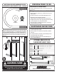
VRSBR14
(4) 5/16"
Nylock Nut
(2) 5/16” x 2-1/2”ID
U-Bolt
(4) 5/16"
Flat Washer
ABC
VRSBR143, VRSBR144, VRSBR14414
VRSBR12
VRSBR13
VRSBR2-HDG
VRSBR3-HDG
PROVIDING POWER TO FAN
MAINTENANCE INSTRUCTIONS
• Disconnect power before cleaning or maintaining your fan in order
to prevent serious injury or death.
• Service and repair of fan should only be completed by a qualified
technician.
• For maximum efficiency and fan life, keep the following free from
dirt and dust: blades, motor and guard.
• The totally enclosed air over motor has sealed ball bearings and
does not require additional oil.
Instructions for corded models
• Provide a grounded outlet that meets or exceeds the load capability
for your fan.
Wiring instructions for non corded models
• Wiring should only be performed by a trained electrician to prevent
injury or death.
• Install manual disconnect switch inside building adjacent to fan.
• Route wire to motor with drip loop and secure.
Drip loop will drain accumulated moisture away from the motor.
• Configure internal wires to match supply voltage and wire according
to motor nameplate. Test to verify correct rotation.
• Only permit power to unit when guard and motor’s cover plate is
properly installed to prevent injury.
Part #
Side Mount Brackets
VRSBR14
VRSBR143
VRSBR144
VRSBR14412
VRSB901
Ceiling Mount Brackets
VRSBR2-HDG
VRSBR3-HDG
Pole Mount Bracket
VRSBR12
VRSBR13
________________________________________________
________________________________________________
________________________________________________
________________________________________________
________________________________________________
________________________________________________
________________________________________________
________________________________________________
________________________________________________
________________________________________________
________________________________________________
________________________________________________
Fan Size
12”-36”
12”-36”
12”-36”
12”-36”
12”-36”
12”–24”
36”
12”-36”
12”-36”
Description
42” Extended Bracket, fits Square or Round Up Post
42” Extended Bracket, fits 3” Tube – Bolt On
42” Extended Bracket, fits 4” Tube – Bolt On
42” Extended Bracket, 4½” Tube – Bolt On
Wall Mount Bracket
6-Way Bracket
6-Way Bracket
Pole Bracket, fits 4”–4½” Tube
Pole Bracket, fits 3”–3½” Tube
ADDITIONAL INCLUDED HARDWARE FOR THE
GREEN BREEZE AND EZ-BREEZE FANS - TO SCALE
Using the installation hardware shown above you can mount the included
bracket as shown below. Drawing “C” is acceptable without contradicting
the space requirement mentioned in step 1 on page 2 as long as there is
nothing behind the pipe to impede air flow. Use (2) 5/16” flat washers and
(2) 5/16” nylock nuts for each u-bolt used, assembled as shown below in
drawing A.
OPTIONAL BRACKETS FOR
FLAG MOUNT BASKET FANS
Visit our website at www.jdmfg.com
2b
DISCONNECT POWER
BEFORE INSTALLING OR SERVICING.
ALL ELECTRICAL WORK SHOULD BE COMPLETED BY
QUALIFIED PERSONNEL AND MEET NATIONAL (NEC),
REGIONAL AND LOCAL ELECTRIC CODES.
! !