
Datasheet


IRG4PC40WPbF
www.irf.com 7
480V
4
X I
C
@25°C
D.U.T.
50V
L
V *
C
Q
R
* Driver same t
y
p
e as D.U.T.; Vc = 80% of Vce
(
max
)
* Note: Due to the 50V
p
ower su
p
p
l
y
,
p
ulse width and inductor
will increase to obtain rated Id.
1000V
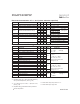
Fig. 13a - Clamped Inductive
Load Test Circuit
Fig. 13b - Pulsed Collector
Current Test Circuit
480µF
960V
0 - 480V
R
L
=
t=5µs
d(on)
t
t
f
t
r
90%
t
d(off)
10%
90%
10%
5%
V
C
I
C
E
on
E
off
ts on off
E = (E +E )
Q
R
S
Fig. 14b - Switching Loss
Waveforms
50V
Driver*
1000V
D.U.T.
I
C
C
V
Q
R
S
L
Fig. 14a - Switching Loss
Test Circuit
* Driver same type
as D.U.T., VC = 480V