
Product Manual


28
For diagnostic and troubleshooting assistance, call Meritor WABCO at 1-800-535-5560
Blink
Code
Problem Area Action
3 Sensor BUI
Determine sensor location. Check sensor installation.
Make necessary repairs.
4 Sensor YEI
Determine sensor location. Check senor installation.
Make necessary repairs.
5 Sensor BU2
Determine sensor location. Check sensor installation.
Make necessary repairs.
6 Sensor YE2
Verify proper electrical modulator installation.
Check power supply. Make necessary corrections.
7 External ABS Modulator Valve
Verify proper electrical modulator installation.
Check power supply. Make necessary corrections.
9
Internal modulator
failure inlet valve #2
Verify proper installation. If code continues, contact
Meritor WABCO for assistance.
10
Internal modulator
failure inlet valve #1
Verify proper installation. If code continues, contact
Meritor WABCO for assistance.
11
Internal modulator
failure inlet valve
Verify proper installation. If code continues, contact
Meritor WABCO for assistance.
14 Power Supply
Verify proper electrical installation. Check power supply. Make
necessary corrections.
15 ECU Failure
Verify proper installation. If code continues, contact Meritor
WABCO for assistance.
16 SAE JI 708 Failure Internal failure, contact Meritor WABCO
17
SAE J2497
(PLC) Failure
Internal failure, contact Meritor WABCO
18 Generic I/O Failure
Verify proper electrical installation. Check power supply. Make
necessary corrections.
9.1 MERITOR/WABCO BLINK CODES
To access Meritor/WABCO blink codes, you must select the Auxiliary Circuit to
power ON/OFF/ON in one second intervals using the following directions:
1. Make sure trailer is stationary and wheels are properly chocked.
2. On the MUTT
®
, turn the control knob to the Auxiliary Circuit. Pause one second.
3. Turn the control knob to the Ground Integrity Indicator (one position to the right).
Pause one second.
4. Turn the control knob back to the Auxiliary Circuit (one position to the left).
5. Count number of blinks on the trailer ABS lamp. Use the chart below for specifi c
fault information.
13
PART 6: GENERAL CONTROLS AND OPERATIONS
6.1 INITIAL STARTUP AND SHUTDOWN
All functions of the MUTT
®
, including air brake controls, require the Power Source
Switch to be in BATTERY or EXTERNAL position.
POWERING UP
1. Push the Power Source Switch to BATTERY or EXTERNAL.
POWERING DOWN
1. Prior to shutting down, exhaust all air from the brake lines, and return all air control
switches to the CLOSED position.
2. Push the Power Source Switch to the OFF position.
NOTE: Turning the power off will disengage the service brakes but NOT the
emergency/parking brakes. Exhausting the Emergency Side air will engage the
spring/parking brakes. See pg. 26 for exhausting/dumping air pressure.
6.2 AUTO SHUTDOWN FEATURE
If left inactive for a period of 20 minutes, the MUTT
®
enters a Sleep Mode and
powers down.
• A sound is emitted every 20 seconds during Sleep Mode.
• Activation of the control knob will cancel Sleep Mode.
0
DC
AMPERES
30
1
0
2
0
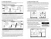
Set Power Source to BATTERY or EXTERNAL
0
DC
AMPERES
30
1
0
2
0
AM
Set Power Source to OFF