
Wiring Diagrams


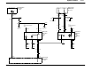


Speed Control31 -3
Hotatall
times
F1.35
15A
BK/LG
3049
Run/Accessory
relay
151−8
3
C2312
C2312
1
25
BK
57
G101
10−4
See page
S205
Ignition switch
(11572)
0) Off
1) Acc
2) Run
3) Start
4) Lock
13−8
C250
3
C250
1
BK/LG
297
4
0
2
1
3
C110
17
LG/VT
1050
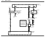
Hotatall
times
F1.12
20A
S219
13−9
See page
PK/BK
489
C134
7
BK/LG
3049
60−3
See page
S212
C1025
1
Brake pressure
switch (2B264)
0) Brake pedal
released
1) Brake pedal
depressed
151−7
10
C1025
2
C175c
16
C139
8
LB/RD
535
C110
6
LG
Power Distribution
Center (PDC)
11−1, 13−3, 13−7, 13−8
F1.10
20A
511
Engine Control
Module (ECM)
23−1, 23−3
C278
4
02
Brake pedal position
switch (13480)
0) Brake pedal de-
pressed
2) Brake pedal re-
leased
151−7
C278
3
Hotatall
times
LG/RD
10
C133
15
2
02
1
15
C139
2
C110
7
OG/YE
2233
OG/YE
2233
GY
1905
VT/OG
298
A
31−2
See page
Additional speed control
deactivation device should
brake switch fail. Depressing
brake pedal with additional
pressure creating 125psi in
brake line, causes brake
pressure switch to open,
thereby removing voltage
and current from electric
clutch within speed control
servo.
90−2
T urn Signal/Stop/
Hazard Lamps
RD/YE
1820