
Wiring Diagrams
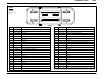


Connector Views150-9
C175a
12A581
Engine Control
Module (ECM)
Pin Circuit Circuit function
1 1683 (DG) switched power
2 1683 (DG) switched power
3 − not used
4 351 (BN/WH) Reference voltage
5 − not used
6 248 (TN/OG) Speed control On input
7 − not used
8 − not used
9 − not used
10 − not used
11 − not used
12 1285 (RD/LG) Idle validation switch input
13 − not used
14 − not used
15 787 (PK/BK) Fuel pump monitor
16 − not used
17 658 (PK/LG) Customer Access
18 1283 (TN/YE) Throttle Position Sensor (TPS) signal
19 − not used
20 914 (TN/OG) ATA +
21 915 (PK/LB) ATA −
22 − not used
23 − not used
24 359 (GY/RD) Signal return
FEMALE
8
16
24
1
9
17
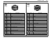
C175b
12A581
Engine Control
Module (ECM)
Pin Circuit Circuit function
1 327 (BK/OG) Water−in−fuel sensor signal
2 − not used
3 1856 (GY/OG) Voltage supplied in Start and Run (overload protected)
4 − not used
5 1769 (BN/PK) PCM power relay, control
6 574 (BK/PK) Ground
7 574 (BK/PK) Ground
8 199 (LB/YE) Transmission range sensor (TR−P) signal
9 1842 (OG/LG) Fuel pump relay, control
10 348 (VT) A/C demand signal
11 76 (LG/WH) Customer Access
12 1851 (WH/LG) Medium speed CAN +
13 1852 (PK/LG) Medium speed CAN −
14 133 (BK) Speed control Cruise resume input
15 − not used
16 − not used
17 679 (GY/BK) Customer Access
18 − not used
19 2231 (LB/RD) Customer Access
20 2232 (RD/LB) Customer Access
21 5133 (WH) Speed control Set input
22 321 (GY/WH) A/C clutch relay, control
23 1093 (TN/RD) Starter relay, control
24 1282 (TN/OG) Barometric Absolute Pressure (BAP) sensor signal
FEMALE
8
16
24
1
9
17
/