
Installation Guide


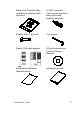
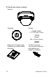


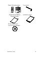

Table Of Contents
- Introduction
- Installation
- Installation environment
- Package contents
- Cable requirements
- Camera description
- Setting up the camera
- Accessing the SD card
- Mounting the IP fixed lens bullet camera
- Mounting the IP VF lens bullet camera and the IP motorized lens bullet camera (without the supplied back box)
- Mounting the IP VF lens dome camera and IP motorized lens dome camera
- Mounting the IP fixed lens dome camera
- Mounting the IP wedge dome camera
- Mounting the IP turret camera
- Using the camera with a recorder
- Using the camera with TruVision Navigator
- Specifications
- Pin definitions

16 Installation Guide
IP motorized lens dome camera
Camera:
Drill template:
Screws:
Drywall anchor
7.5 × 24.5 mm (4 pcs)
Screw
M4 × 25 mm (4 pcs)
Screws: M4 × 9 (3 pcs)
Mounting adaptor plate:
Water joint: Provides water
resistance to network cable
connector.
12 VDC connector:
Two terminal connector
with positive and
negative indicators.