
User's Manual


Installation Manual the Multiplexer 17-11
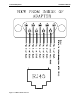
Multiplexer board settings
Use the board settings below (Table 17.1 and Figure 17.9)
for Dip Switch S2 on the Multiplexer.
NOTE:
Only board 1 (Address 0000) should be plugged
into the PC.
Table 17.1 Multiplexer Board Settings
Board Number Dip Switch Setting
1234
1 0000
2 0001
3 0010
4 0011
5 0100
6 0101
7 0110
8 0111
9 1000
10 1001
11 1010
12 1011
13 1100
14 1101
15 1110
16 1111
Figure 17.9 Multiplexer Switch Settings