
Installation Instructions


P03-R01-0704
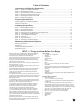
Right (Black)
Cable Drum
Black Winding
Cone
Center Bearing Plate
Stationar
y
Cone
Standard Torsion Spring System
Left (Red)
Cable Drum
End Bearing Plates
Red Winding
Cone
Torsion Tube
EZ-Set™ Extension Spring System
EZ-Set™ Winding Unit
Sheave
Standard Extension Spring System
Stationary Sheave
Sheave
NOTE: The above illustration represents a composite of many of the features found on a variety of garage doors. While not
representative of any one door, it provides a handy reference for the location of speci c components
8
EZ-Set™ Torsion Spring System
EZ-Set™
Winding Unit
Left Cable Drum
EZ-Set™ Bracket
Containment Cable
Typical Garage Door Installation Illustration
Extension Spring System Shown on Complete Door
Rear Track Hanger
(Not Included)
Extension Spring
Sheave
Stationary Sheave
Horizontal Track
Door Jamb
Flag Bracket
Vertical TrackVertical Track
Top Bracket
#3 Hinge
#2 Hinge
#1 Hinge
#1 Hinge
#1 Hinge
#1 Hinge
#1 Hinge
#1 Hinge
#1 Hinge
Inside Step
Plate
Inside Step
Plate
Inside Step
Plate
Inside Step
Plate
#3 Hinge
#2 Hinge
#1 Hinge
Long Track Bracket
Short Track Bracket
Safety Label
Bottom Brackets
Section #3
Section #4
Safety Label
Section #2
Section #1
P03-R01-0704
STEP 9 - Installing Door Sections
(Continued)
Step 9-6: Place the second section on top of the rst section.
Drive a 3” nail in the jambs at each end and bend it over the
edges of the section to hold the section in place. Attach the
hinges from the top of the rst section to the bottom of the
second. (FIG. 9-D)
Step 9-7: Place the third section on saw horses. Attach #3
hinges to the ends at the top edge and #1 hinges to all other
stiles along the top edge using #14 x 5/8” sheet metal screws.
(FIG. 9-E)
NOTE: If your door was supplied with more than 1 strut
(consult Table 7-A on bottom of page 10), use 1/4” x 3/4” self
tapping screws to attach strut as shown in the illustration.
When pre-drilled holes in strut do not line up vertically with
stiles, you will be required to drill (2) 3/16” pilot holes through
the strut and the stile at each end stile and each center stile,
or use a drill or impact wrench with a 7/16” socket to drive
self-tapping screws through strut and stile. (FIG. 9-E)
Step 9-8: Place the third section on top of the other sections
and nail in place as before. Attach the hinges from the top of
the previous section to the bottom of this section. (FIG. 9-D)
If you have two sections left, repeat Steps 9-7 and 9-8 using
#4 hinges on the end of the top edge and #1 hinges to all other
stiles along the top edge.
Step 9-9: Place the last section on the saw horses. Attach the
top roller brackets as shown. The top roller brackets are to be
attached with three (insulated doors) or four (non-insulated
doors) #14 x 5/8” sheet metal screws. The top of the bracket
should be located 3-1/4” down from the top of the door. The
bottom of the bracket goes in smaller holes 6-1/4” from top of
section. (FIG. 9-F)
If your door was supplied with any struts (consult Table 7-A
on bottom of page 10), use 1/4” x 3/4” self tapping screws
to attach strut as shown in the illustration. When pre-drilled
holes in strut do not line up vertically with stiles, you will be
required to drill (2) 3/16” pilot holes through the strut and the
stile at each end stile and each center stile, or use a drill or
impact wrench with a 7/16” socket to drive self-tapping screws
through strut and stile. (FIG. 9-F)
Step 9-10: Place a roller in the top and bottom brackets and
in the tubes in each of the hinges at the ends of each section.
Some hinges have two tubes. Place the roller in the tube that is
farthest from the face of the door. (FIG 9-G)
Safety
Label
FIG. 9-D
FIG. 9-E
13
Top Bracket
#1 HingeBottom Bracket
#2, 3, or 4 Hinge
FIG. 9-G
1/4" x 3/4"
Self Tapping Screws
Strut
(
if necessar
y)
#3 Hin
g
e
#1 Hin
g
e
3