
User's Manual


2
Safe ty Rules ..........................................2-3
Warranty ................................................4-7
Prod uct Spec i fi ca tions .............................. 8
Assembly / Pre-Operation ........................9
Op er a tion ........................................... 10-13
Maintenance Sched ule ........................... 14
Maintenance ......................................14-16
Ser vice and Ad just ments ...................17-18
Stor age ..............................................18-19
Trou ble shoot ing .................................19-20
Re pair Parts .......................................40-47
TABLE OF CONTENTS
IMPORTANT: This cutting machine is capable of amputating hands and feet and throwing ob-
jects. Failure to observe the following safety instructions could result in serious injury or death.
Look for this symbol to point out im-
por tant safety precautions. It means
CAU TION!!! BECOME ALERT!!!
YOUR SAFE TY IS INVOLVED.
WARNING: In order to prevent ac ci den tal
starting when setting up, trans port ing, ad-
just ing or making repairs, always dis con nect
spark plug wire and place wire where it can not
come in contact with plug.
WARNING: Engine exhaust, some of its
constituents, and certain vehicle com po -
nents contain or emit chem i cals known to
the State of Cal i for nia to cause can cer and
birth defects or oth er re pro duc tive harm.
WARNING: Battery posts, terminals and
related accessories contain lead and lead
compounds, chemicals known to the State
of Cal i for nia to cause can cer and birth
defects or oth er re pro duc tive harm. Wash
hands after handling.
CAUTION: Muffl er and other engine
SAFETY RULES
parts become extremely
hot during operation and
remain hot after engine
has stopped. To avoid
severe burns on contact,
stay away from these areas.
I. GENERAL OPERATION
• Read, understand, and follow all
in struc tions on the machine and in the
manual(s) before starting. Be thor ough ly
familiar with the controls and the proper
use of the machine before starting.
• Do not put hands or feet near or under
rotating parts. Keep clear of the dis-
charge opening at all times.
• Only allow responsible individuals, who
are familiar with the in struc tions, to
operate the machine.
• Clear the area of objects such as rocks,
toys, wire, bones, sticks, etc., which could
be picked up and thrown by blade.
• Be sure the area is clear of other people
before mowing. Stop the ma chine if
anyone enters the area.
• Do not operate the mower when bare-
foot or wearing open sandals. Al ways
wear substantial foot wear.
• Do not pull mower backwards unless abso-
lutely nec es sary. Always look down and be-
hind before and while moving backwards.
• Never direct discharged material toward
anyone. Avoid discharging material
against a wall or obstruction. Material may
richochet back toward the operator. Stop
the blade when crossing gravel surfaces.
• Do not operate the mower without prop-
er guards, plates, grass catcher or oth er
safety protective devices in place.
• See manufacturer’s instructions for
proper operation and installation of
accessories. Only use accessories ap-
proved by the manufacturer.
• Stop the blade(s) when crossing grav el
drives, walks, or roads.
• Stop the engine (motor) whenever you
leave the equip ment, before clean ing
the mower or unclogging the chute.
• Shut the engine (motor) off and wait
until the blade comes to complete stop
before removing grass catcher.
• Mow only in daylight or good artifi cial light.
• Do not operate the machine while under
the infl uence of alcohol or drugs.
• Never operate machine in wet grass.
Always be sure of your footing: keep a
fi rm hold on the handle; walk, never run.
• Disengage the self-propelled mech-
a nism or drive clutch on mowers so
equipped before starting the engine.
• If the equipment should start to vi brate
abnormally, stop the engine (motor) and
check immediately for the cause. Vibra-
tion is generally a warning of trouble.
• Always wear safety goggles or safe ty glass-
es with side shields when op er at ing mower.
II. SLOPE OPERATION
Slopes are a major factor related to slip &
fall accidents which can result in severe
injury. All slopes require extra caution. If
you feel uneasy on a slope, do not mow it.
47
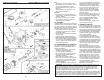
MODEL NUMBER GCV-160-LAOS3AHONDA 4-CYCLE ENGINE
CAMSHAFT PULLEY
KEY PART
NO. NO. DESCRIPTION
1 14320-ZL8-010 Pulley, Camshaft
2 14324-ZL8-000 Shaft, Cam Pulley
3 14400-Z0J-014 Belt, Timing
(84HU7 G-200)
6 14461-ZL8-000 Shaft, Rocker Arm
11 90112-333-000 Screw, Tappet Adjusting
12 90206-001-000 Nut, Tappet Adjusting
13 91301-ZM0-V31 O-Ring (6.8 x 1.9) (ARAI)
15 14431-Z0J-000 Rocker Arm, Intake Valve
16 14441-Z0J-000 Rocker Arm,
Exhaust Valve
OIL PAN
KEY PART
NO. NO. DESCRIPTION
1 11300-ZM0-811 Pan Assembly, Oil
2 15650-ZM0-801 Gauge Assembly,
Oil Level
4 15625-ZE6-000 Gasket, Oil Filler Cap
5 15631-ZM0-000 Extension, Oil Filler
6 15639-ZM0-000 Lock Washer, Extension
8 16508-ZM0-010 Shaft, Governor Holder
9 16510-ZM0-010 Governor Assembly
10 16511-ZL8-000 Weight, Governor
11 16512-ZM0-000 Holder, Governor Weight
12 16513-ZE1-000 Pin, Governor Weight
13 16531-ZE1-000 Slider, Governor
14 16541-ZM0-000 Shaft, Governor Arm
15 90014-952-000 Bolt, Flange (#6 x 14)
(CT200)
16 90121-952-000 Bolt, Flange (#6 x 25)
(CT200)
17 90451-ZE1-000 Washer, Thrust (6 mm)
18 90602-ZE1-000 Clip, Governor Holder
19 91202-ZL8-003 Oil Seal (28 x 41.25 x 6)
20 91356-MA6-005 O-Ring (14.8 x 2.4) (NOK)
21 94101-068000 Washer, Plain (6 mm)
22 94251-08000 Pin, Lock (8 mm)
23 94301-08200 Pin, Dowel (#8 x 20)
PISTON / CONNECTING ROD
KEY PART
NO. NO. DESCRIPTION
1 13101-Z2A-010 Piston
2 13111-ZE0-000 Pin, Piston
3 13200-Z0J-000 Connecting Rod Assembly
4 90001-ZE1-000 Bolt, Connecting Rod
5 90551-ZE0-000 Clip, Piston Pin (13 mm)
6 13010-Z0L-014 Ring Set, Piston, Standard
(Teikoku)
LABELS
KEY PART
NO. NO. DESCRIPTION
9 87528-Z0L-V20 Mark, Choke Indication
20 87114-ZH7-821 Label, Warning
30 87101-Z8B-000 Mark, Emblem (GCV160)
31 87169-Z8E-000 Mark, Recoil Cover
32 87524-Z8B-000 Mark, Caution,
Fuel Petcock
CHOKE BASE
KEY PART
NO. NO. DESCRIPTION
2 16592-Z2D-800 Spring, Return
5 16614-Z2D-800 Spring, Choke Lever
8 16632-Z0L-801 Rod, Stop
9 90022-888-010 Bolt, Flange (#6 x 20)
(CT200)
14 16610-Z2D-801 Lever Assembly, Choke
16610-Z2D-802 Lever Assembly, Choke