
Specifications


Q2431-90912 Chapter 6 Removing and replacing parts 163
Output delivery assembly
1. Remove the following assemblies:
● Top cover. See “Top cover” on page 146.
● Rear output bin. See “Rear output bin” on page 155.
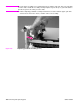
2. Release the locking pin on the shaft lock and rotate the lock toward the rear of the printer
until the inner retaining tab (gear side) aligns with the hole in the output delivery assembly
frame. Slide the shaft lock to the right and remove it to release the gear shaft from the output
delivery assembly.
Hint Snap the shaft lock back into place on the assembly so that you will not lose it. Remove the shaft
lock when you reinstall the output delivery assembly. When the output delivery assembly is
installed, verify that the locking pin on the shaft lock is fully seated in the hole on the output delivery
assembly.
Figure 102. Output delivery assembly (rear view, formatter side; 1 of 2)