
HP StoreAll Storage Network Best Practices Guide


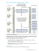

Table Of Contents
- HP StoreAll Storage Network Best Practices Guide
- Contents
- 1 Overview of HP StoreAll Storage networking
- 2 StoreAll 9730 platform networking
- 3 StoreAll 93xx/8x00 platform networking
- 4 Expanding an existing cluster
- 5 Support and other resources
- 6 Documentation feedback
- A BOND modes
- B StoreAll 93xx 10 GbE bonding modes and switch interconnection
- C Install and the default Virtual Connect configuration

StoreAll node physical hardware mapping
Table 5 (page 35) shows the mapping of the logical networks to the server blade and VC
interconnect hardware.
Table 5 StoreAll 9730 flat network — physical mapping
Connection Type
VC External
ConnectionVC Module
Node
Physical
Interface
Allocated
Bandwidth
Node
InterfaceNetwork
Primary External
Connection
X6Interconnect Bay
1
eth 010 GbBond0User,
Cluster,
Management
LACP trunking with X6X5, X4, X3, X2,
X1
Primary External
Connection
X6Interconnect Bay
2
eth 3
LACP trunking with X6X5, X4, X3, X2,
X1
Physical cabling
The minimum cabling required to attach an StoreAll 9730 enclosure to a customer network consists
of the four patch cables shown in Figure 10 (page 35). For maximum redundancy, each patch
cable ideally connects to a physically separate edge switch in the customer network.
Figure 10 StoreAll 9730 flat network — minimum cabling
Table 6 (page 36) summarizes the necessary connections.
Flat network 35