
HP StorageWorks Enterprise Virtual Array 3000/5000 User Guide VCS 3.x (5697-5480, March 2006)


0112a
Front
Rear
1
2
3
4
56 78 9
10
10
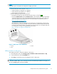
Figure 10 FC drive enclosure—front and rear views
1. Drive bay 1 2. Drive bay 14
3. EMU
4. I/O module B
5. Blower 1 6. Power supply 1
7. Blower 2 8. Power supply 2
9. I/O module A
10. Status indicators (EMU, enclosure power,
enclosure fault)
I/O modules
Two I/O m
odules provide the interface between the drive enclosure and the host controllers. See Figure
11.They
route data to and from the disk drives using Loop A and Loop B, the dual-loop configuration.
For redundancy, only dual-controller, dua l-loop operation is supported. Each controller is connected to
both I/O modules in the drive enclosure.
44
Enterprise Virtual Array hardware components