
HP StorageWorks 2012sa Modular Smart Array user (488320-004, March 2013)


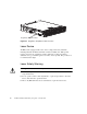
Table Of Contents
- Contents
- About This Guide
- 1
- System Components
- 2
- Installing and Cabling Enclosures
- 3
- Connecting Hosts
- 4
- Configuring a System for the First Time
- 5
- Troubleshooting
- Fault Isolation Methodology
- Correcting Enclosure IDs
- Using System LEDs to Diagnose Problems
- Is the front panel Fault ID amber?
- Is the controller back panel OK LED off?
- Is the controller back panel Fault/Service Required LED amber?
- Are both drive module LEDs, Online/Activity, and Fault/UID LEDs off?
- Is the drive module Fault/UID LED blinking amber?
- Is a connected port’s Host Link Status LED off?
- Is a connected port’s Expansion Port status LED off?
- Is a connected port’s Ethernet link status LED off?
- Is the power-and-cooling module AC Power Good LED off?
- Is the power-and-cooling module DC Voltage/Fan Fault/Service Required LED amber?
- Is the drive enclosure back panel OK LED off?
- Is the drive enclosure Fault/Service Required LED amber?
- Isolating a Host-Side Connection Fault
- Isolating a Controller Module Expansion Port Connection Fault
- Resolving Voltage and Temperature Warnings
- A
- Environmental Requirements and Specifications
- B
- Regulatory Compliance and Safety
- Index
76 HP 2012sa Modular Smart Array user guide • January 2013
Electrical Requirements
Site Wiring and Power Requirements
Each enclosure has two power and cooling modules for redundancy. If full
redundancy is required, use a separate power source for each module. The AC
power supply unit in each power and cooling module is auto-ranging and is
automatically configured to an input voltage range from 88–264 VAC with an input
frequency of 47–63 Hz. The power and cooling modules meet standard voltage
requirements for both U.S. and international operation. The power and cooling
modules use standard industrial wiring with line-to-neutral or line-to-line power
connections.
Power Cord Requirements
Each enclosure is shipped with two AC power cords that are appropriate for use in
a typical outlet in the destination country. Each power cord connects one of the
power and cooling modules to an independent, external power source. To ensure
power redundancy, connect the two power cords to two separate circuits; for
example, to one commercial circuit and one uninterruptible power source (UPS).