
HP PCL/PJL reference (PCL 5 Printer Language) - Technical Reference Manual Part II


EN Using Scaling Effectively 19-15
Adapting the HP-GL/2 Coordinate System to
Match the PCL System
The following example uses the IP and SC commands to change
HP-GL/2 coordinate system to match the default PCL coordinate
system. The IP command is used to invert the Y-axis so that the Y
values increase as the pen moves down the page. The SC command
equates user-units to dot positions (300 dots-per-inch). The example
draws a few lines in both PCL and HP-GL/2 modes to demonstrate
that the coordinate systems are lined up correctly (the end points of
the lines intersect).
Notes Sending an IN (Initialize) or DF (Default) command causes the
coordinate system to revert to the HP-GL/2 default.
Since this example is based on the default top margin and text length,
changing the top margin or the text length moves the two coordinate
systems out of alignment.
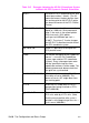
Table 19-5 Example: Adapting the HP-GL/2 Coordinate System
to Match the PCL System in Portrait Orientation
E
C
E Reset the printer.
E
C
&l2A Set the page size to letter.
E
C
&l0O Specify portrait orientation.
E
C
&l0E Set top margin to 0.
E
C
*p0x0Y Move to position (0,0).
E
C
*c5760x7920Y Set picture frame to 8’’ x 11’’ (size of
logical page).
E
C
*c0T Set picture frame anchor point to
current PCL cursor position (0,0).
E
C
%1B Enter HP-GL/2 mode with the HP-GL/2
cursor or pen at the PCL cursor
position.