
HP Enterprise Virtual Array 6400/8400 Expansion Rack Reference Guide (5697-1818, March 2012)
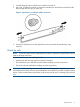


d. Connect P2 (I/O-B) on S-26 to P1 (I/O-B) on S-27.
4. Connect the rack power distribution units to a power source.
5. Using a power cord provided in your kit, plug one end into a disk enclosure power supply
and the other end into a rack power distribution module. Plug the left power supply into the
left module and the right power supply into the right module.
6. Repeat Step 5 for each disk enclosure in the expansion rack.
7. Power on the rack distribution units.
8. Press and hold the power push button (located at the rear of the disk enclosure) long enough
to power up the disk enclosure.
9. Repeat Step 8 for each disk enclosure in the expansion rack.
Preparing the expansion rack for connection to the main rack
This section contains the preparation steps that must be performed before connecting the expansion
rack and the main rack.
Physically inspect the expansion rack
Physically inspect the expansion rack. Verifying each of the following conditions:
• All enclosures and enclosure modules are properly installed and seated.
• Each power supply is connected to one of the electrical outlets in the rack.
• The end connector of each cable is plugged into a disk enclosure I/O module.
Inspect expansion rack disk drives
After the expansion rack is powered up, ensure that all disk drives are fully engaged and seated
in their associated enclosures. Observe the disk drive status indicators to ensure that the disks are
working properly. The status indicators will be amber or blue depending on the condition of the
disk enclosure. See Figure 20 (page 20) for the location of the disk drive indicators and
Table 3 (page 21) for a description of the indicators.
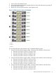
Figure 20 Disk drive status indicators
1. Bi-color (amber/blue)
2. Green
20 Installing disk enclosures into the expansion rack