
HP 3PAR F-Class, T-Class, StoreServ 10000 Storage Troubleshooting Guide (QL226-96953, May 2013)

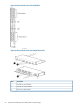


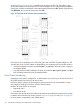


Table 8 Fan Module Configuration Based Upon System and Number of Controller Nodes
Fan ModulesController NodesSystem
4210400
84
4210800
84
126
168
The illustration explains the numbering scheme for the fan modules within a controller node.
Figure 48 Fan Module Numbering Scheme, Single Phase and 3–Phase PDU
Battery Module Numbering
Depending on the controller node configuration, the controller node chassis may include one or
two battery compartments to situate the battery modules. The battery modules supply enough power
to write the cache memory to the drive inside the nodes during a power failure.
Each controller node requires an associated battery module for all configurations (Figure 9
(page 45)).
44 Component Numbering for HP 3PAR StoreServ 10000 Storage