
DisplayMaker Legacy 72S and 72SR - User Manual


5-14 Set the Printhead and Camera Height
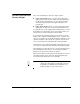
13. Loosen the three camera enclosure mounting screws (see Fig.
5-8 below).
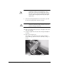
14. Set the camera height.
Insert the plain (non-stepped) end of the gauge as shown in
Fig. 5-9 below.
Raise or lower the camera enclosure so that it touches the
top of the gauge.
15. Tighten the camera enclosure mounting screws.
16. Replace carriage cover and screws.
17. Press ! to return the carriage to the service station.
The control panel displays a message asking whether you
want to calibrate the service station. See “Calibrate the Ser-
vice Station” on page 5-16 for instructions.
18. Press
" to calibrate the service station, or ( to continue.
Fig. 5-8. Camera enclosure mounting screws
(recessed)
Fig. 5-9. Camera height measurement point
Camera enclosure