
Product Overview


23 60-2507—3
W7100A-E
(continued)
SETTINGS AND ADJUSTMENTS • SYSTEM CHECKOUT
Settings and Adjustments
SETPOINT KNOB: Set for desired discharge air tempera-
ture (55° F to 60° F [13° C to 16° C] is typical).
RESET KNOB: Set for desired cool reset (outer scale) or
heat reset (inner scale) as required (20° F [11° C] typical).
CONTROL BAND KNOB: Set for desired control band.
Increasing the control band setting slows down the
machinery and increases the temperature deviation. Turn-
ing down the control band to a lower setting speeds up
the machinery and reduces the temperature deviation.
Refer to Table 5.
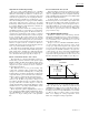
TABLE 5—RECOMMENDED
STARTING CONTROL BAND SETTING.
ECONOMIZER CHANGEOVER OPTION.
In installations using an economizer and enthalpy con-
trol, an outdoor air changeover controller limits the econo-
mizer to the minimum position when enthalpy is above
setpoint. Set the H205 dial to the A position.
SETTING NUMBER OF CONTROLLED STAGES
A fixed resistor is installed across the number of stages
input (terminals 7 and 8). The resistor value tells the W7100
how many stages of heating and cooling are to be con-
trolled. This affects the control behavior and determines
how many stages the W7100 will turn on and off.
A 400 or 600 ohm resistor is initially installed on termi-
nals 7 and 8. This corresponds to the value for controlling
four or six stages of heating or four or six stages of cooling.
If the system being installed has more or fewer stages of
heating and cooling, this resistor must be changed to the
value shown in Table 2. These resistors are contained in
4074EFV Bag Assembly , available separately (see W7100
System Accessory Chart). The new value will represent the
actual number of switched heating/cooling stages operat-
ing under control of the W7100. This includes any stages
on a W7101A Sequencer connected to the W7100 control.
Refer to Table 2.
Number of Changes
246810
VAV Cooling 86432
VAV Heating 16 12 8 6 4
The controller range should be as narrow as possible
without causing hunting or rapid cycling, regardless of load
conditions. If instability or hunting occurs at the sug-
gested setting, widen the control band.
Step Action Verification
1 Open electrical disconnects on compressors —
2 Connect 195770A Test Plug from 4074EDJ Bag
Assembly to W7100 to disable most time delays. Jumper
remote setpoint potentiometer terminals P-P1 and jumper
reset terminals 6 and 7. Be sure that heating changeover
terminals 9 and 10 are open. Set control band initially to
10° F.
—
3 Disconnect C7100 sensor from terminals T-T1. Connect
3400 ohm resistor (blue leads) from 4074EDJ Bag
Assembly at terminals T-T1 to simulate 60° F [16° C]
discharge temperature. Adjust setpoint knob to 56° F
[13° C]. If an economizer is not used, connect terminal 9
to Y through a 510 ohm resistor.
—
4 Apply power. For W7100 with economizer and without
510 ohm resistor.
After about two minutes, the LEDs should
indicate that cooling outputs are staging on. (The
economizer requires this time to go fully open.)
5 Adjust the setpoint knob to 64° F [18° C]. After
verification, immediately proceed to step 6.
Cooling LEDs should indicate staging off in
about ten seconds.
System Checkout
Use Table 6 to perform a checkout of the W7100 Controller in the cooling mode.
TABLE 6—W7100 CONTROLLER CHECKOUT, COOLING MODE.