
Installation Guide


THP2400A1019 COVER PLATE ASSEMBLY
3 69-2762EFS—01
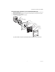
Mount Cover Plate to a Vertical 2 in. X 4 in. Electrical Box (See Fig. 3)
1. Position the bracket on the electrical box. Insert two #6-32 X 5/8 flat head screws. Check leveling, if desired, and
tighten the flat head screws.
2. Pull the wires through the wire hole on the cover plate and wall plate. Position the cover plate and wall plate on
the bracket with the arrows pointing up.
3. Insert two #6-32 X 1/4 pan head screws and tighten.
Fig. 3. Mount bracket, cover plate, wall plate and thermostat to a vertical 2 in. X 4 in. electrical box.
#6-32 X 5/8 FLAT
HEAD SCREWS (2)
ELECTRICAL BOX
BRACKET
WIRE
WIRE HOLE
COVER PLATE
MOUNTING HOLES (2)
#6-32 X 1/4 PAN
HEAD SCREWS (2)
THERMOSTAT
WIRE HOLE
WALL PLATE
MOUNTING HOLES (2)
M34260