Quick Installation Guide RTHL3550 Non-programmable Thermostat 69-2584ES-01
Installation is Easy Label wires and remove your old thermostat Install and wire your new thermostat Set your new thermostat to match your heating/ cooling system – It is preset for the most common system We are here to help. Call 1-800-468-1502 for wiring assistance before returning the thermostat to the store.
1 Turn Off Power to Heating/ Cooling System M28097 1 69-2584ES—01
2 Remove Old Thermostat Remove old thermostat but leave wallplate with wires attached. Leave wallplate in place Is there a sealed tube containing mercury? If so, see notice below for proper disposal instructions. Old thermostat Cover M28099 MERCURY NOTICE: Do not place your old thermostat in the trash if it contains mercury in a sealed tube. Contact the Thermostat Recycling Corporation at www.thermostat-recycle.
3 Label Wires with Tags Label the wires using the supplied wire labels as you disconnect them. M28100 Wire Labels M28093 NOTE: Jumper wire used on old thermostat? If yes, note what letters the jumper connected and review in wiring section.
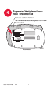
4 Separate Wallplate from New Thermostat Remove battery holder. Pull here to remove wallplate from new thermostat.
5 Mount Wallplate Mount the new wallplate using the included screws and anchors. M28345 Drill 3/32-in. holes for plaster. Drill 3/16-in. holes for drywall. Use hammer to tap the anchors into the wall.
6 Connect Wires Simply match wire labels. Remove metal jumper if you have both R and Rc wires. G W Y2 W2 G W Y Y R R Rc CONVENTIONAL MCR31270 Labels don’t match? See page 24. Have a Heat Pump system? See pages 25-26. We are here to help. Call 1-800-468-1502 for wiring assistance.
7 Install Batteries Install two AA alkaline batteries.
8 Install Thermostat onto Wallplate Install thermostat onto the wallplate on the wall.
9 Turn Power Back On Turn the power back on to the heating/cooling system.
10 If your system type is... If your system type is: q Single Stage Heat and Cool Congratulations, you’re done! If your system type is: q Multistage Heat and Cool q Heat Pump* without Backup Heat q Heat Pump* with Backup Heat q Heat Only q Cool Only Continue with advanced installation on page 12 to match your thermostat to your system type. *Heat Pump—an air conditioner that provides cooling in the summer, and also runs in reverse in the winter to provide heating.
Advanced Installation System setup.......................................................................12 Wiring...................................................................................24 Troubleshooting...................................................................27 Customer assistance..........................................................29 Limited warranty..................................................................
Advanced Installation Guide System setup WIRING SETUP Press and hold the s and FAN buttons until the screen changes (approximately 5 seconds). TROUBLESHOOTING ASSISTANCE MCR32601 Press s or t to change settings. Function Done Setting Next MCR32600 Press DONE to exit and save settings. Press NEXT to advance to next function.
RTHL3550 Function 1: System type Press the s or t button to select the type of system you have in your home: SETUP Done Next MCR32599 1 Heat pump: Outside compressor provides both heating and cooling without backup or auxiliary heat. WIRING 0 Heating & cooling: Gas, oil or electric heating with central air conditioning. 2 Heating only: Gas, oil or electric heating without central air conditioning. 4 Cool only: Central air conditioning only.
Advanced Installation Guide About your Function 2: new Heatthermostat pump changeover valve NOTE: If Function 2 does not appear, please turn to the next page to continue. WIRING SETUP Press the s or t button to select whether your changeover valve is used in heating or cooling: TROUBLESHOOTING ASSISTANCE Done Next MCR32605 0 Cooling changeover valve: Use this setting if you connected a wire labeled “O” to the O/B wire terminal (see page 25).
RTHL3550 About your Function 3: new Heating thermostat fan control Press the s or t button to select your heating system and fan operation: SETUP NOTE: If Function 3 does not appear, please turn to the next page to continue. WIRING Done Next MCR32603 1 Electric heat: Use this setting if you have an electric heating system (thermostat controls fan operation). MCR32602 15 69-2584ES—01 TROUBLESHOOTING Press to change setting. When correct setting is selected, press NEXT to display next function.
Advanced Installation Guide About your Function 5: new Heating thermostat cycle rate NOTE: If Function 5 does not appear, please turn to the next page to continue. WIRING SETUP Press the s or t button to select your heating system and optimize its operation: ASSISTANCE Done Next MCR32604 5 Gas or oil furnace: Use this setting if you have a standard gas or oil furnace that is less than 90% efficient. 9 Electric furnace: Use this setting if you have any type of electric heating system.
RTHL3550 Function 6: Stage 2 Heat cycle rate Press the s or t button to select your heating system and optimize its operation: SETUP NOTE: If Function 6 does not appear, please turn to the next page to continue. WIRING Done Next MCR32606 9 Electric furnace: Use this setting if you have any type of electric heating system. ASSISTANCE 5 Gas or oil furnace: Use this setting if you have a standard gas or oil furnace that is less than 90% efficient.
Advanced Installation Guide Function 8: Emergency heat cycle rate NOTE: If Function 8 does not appear, please turn to the next page to continue. WIRING SETUP Press the s or t button to select your heating system and optimize its operation: TROUBLESHOOTING ASSISTANCE Done Next MCR32608 9 Electric furnace: Use this setting if you have any type of electric heating system. 1 Gas/oil steam or gravity system: Use this setting if you have a steam or gravity heat system.
RTHL3550 About your Function 12:new Manual/Auto thermostatChangeover Press the s or t button to select Manual or Auto Changeover: SETUP Next MCR32609 WIRING Done 0 Manual Changeover: (Heat/Off/Cool) CAUTION: To avoid possible compressor damage, set to option 0 if the outside temperature drops below 50 ºF (10 ºC). Press to change setting. When correct setting is selected, press NEXT to display next function.
Advanced Installation Guide About your Function 14:new Temperature thermostatdisplay WIRING SETUP Press the s or t button to select Fahrenheit or Celsius temperature display: Done Next 0 Fahrenheit temperature display (°F) ASSISTANCE 1 Celsius temperature display (°C) Press to change setting. When correct setting is selected, press NEXT to display next function.
RTHL3550 About your Function 27:new Maximum thermostat heat setting Press the s or t button to select maximum heat temperature setting: SETUP Next MCR32611 WIRING Done 40-90 Maximum heat temperature setting (°F); (4.5°C to 31.5°C) ASSISTANCE Press to change setting. When correct setting is selected, press NEXT to display next function.
Advanced Installation Guide About your Function 28: new Minimum thermostat cool setting WIRING SETUP Press the s or t button to select minimum cool temperature setting: Done Next MCR32612 ASSISTANCE 50-99 Minimum cool temperature setting (°F); (10.5°C to 37°C) TROUBLESHOOTING MCR32602 Press to change setting. When correct setting is selected, press DONE to exit and save changes.
RTHL3550 Wiring—Conventional System C Y2 W2 G X B W F Y W1 H R Y1 M SETUP If labels do not match letters on the thermostat, check the chart below and connect to terminal as shown here (see notes, below). Rc RH 4 V R WIRING Y2 W2 G W Y R Rc If wires will be connected to both R and Rc terminals, remove metal jumper (see page 6). Do not use C, X or B. Wrap bare end of wire with electrical tape.
Advanced Installation Guide About your new Wiring—Heat Pump thermostat 1. Match each labeled wire with same letter on new thermostat. 2. Use a screwdriver to loosen screws, insert wires into hole under screw, then tighten screws until wire is secure. 3. If E and Aux do not each have a wire connected, use a small piece of wire to connect them to each other. 4. Push any excess wire back into the wall opening.
RTHL3550 Wiring—Heat Pump About your new thermostat Alternate wiring (for heat pumps only) SETUP If labels do not match letters on the thermostat, check the chart below and connect to terminal as shown here (see notes, below). 4 5 C E W W1 W2 Aux O F G Y H B O/B R Y1 M Y V VR R Rc R Rc 2 MCR31275A Wiring complete, return to Step 7. 25 69-2584ES—01 TROUBLESHOOTING 5 Leave metal jumper in place, connecting R & Rc terminals.
Advanced Installation Guide TROUBLESHOOTING ASSISTANCE WIRING SETUP Troubleshooting If you have difficulty with your thermostat, please try the following suggestions. Most problems can be corrected quickly and easily. Display is blank • Make sure fresh AA alkaline batteries are correctly installed (see page 7). Make sure heating and cooling Temperature settings do not temperatures are set to acceptable ranges: change • Heat: 40° to 90 °F (4.5° to 32 °C). • Cool: 50° to 99 °F (10° to 37 °C).
RTH6400 Troubleshooting • Compressor protection feature is engaged. Wait 5 minutes for the system to restart safely, without damage to the compressor. Heating system • Check Function 1: System Type to make sure it is set to match your is running in heating and cooling equipment cool mode (see page 13). 27 69-2584ES—01 TROUBLESHOOTING • Check Function 2: Heat Pump Heat pump Changeover Valve to make sure issues cool air it is properly configured for your in heat mode, system (see page 14).
Advanced Installation Guide SETUP Customer assistance For assistance with this product, please visit http://yourhome.honeywell.com or call Honeywell Customer Care toll-free at 1-800-468-1502. WIRING To save time, please remove the battery holder and note your model number and date code before calling. Accessories/replacement parts To order, please call Honeywell Customer Care toll-free at 1-800-468-1502. *Use to cover marks left by old thermostats. TROUBLESHOOTING ASSISTANCE Battery holder.........
RTHL3550 1-year About limited your new warranty thermostat WIRING ASSISTANCE TROUBLESHOOTING 29 69-2584ES—01 SETUP Honeywell warrants this product, excluding battery, to be free from defects in the workmanship or materials, under normal use and service, for a period of one (1) year from the date of purchase by the consumer. If at any time during the warranty period the product is determined to be defective or malfunctions, Honeywell shall repair or replace it (at Honeywell’s option).
MERCURY NOTICE: Do not place your old thermostat in the trash if it contains mercury in a sealed tube. Contact the Thermostat Recycling Corporation at www.thermostat-recycle.org or 800-238-8192 for information on how and where to properly and safely dispose of your old thermostat. CAUTION: To avoid possible compressor damage, do not run air conditioner if the outside temperature drops below 50 °F (10 °C). Automation and Control Solutions Honeywell International Inc.
Guía de instalación rápida RTHL3550 Termostato no programable 69-2584ES-01
¡La instalación es fácil! Rotule los cables y retire el termostato viejo Instale y conecte los cables de su nuevo termostato Ajuste su nuevo termostato para que concuerde con su sistema de calefacción/refrigeración – Está preconfigurado para el sistema más común Estamos aquí para ayudarle. Llame al 1-800-468-1502 para obtener asistencia con el cableado antes de devolver el termostato a la tienda.
1 Desconecte la alimentación en el sistema de calefacción/ refrigeración M28097 1 69-2584ES—01
2 Remueva su viejo termostato Retire el termostato existente pero deje la placa de pared con los cables adheridos. Deje la placa de pared en su lugar ¿Hay un tubo sellado que contiene mercurio? Si es así, consulte en la cubierta de este manual las instrucciones para su desecho apropiado. Termostato viejo Cubierta M28099 AVISO DE MERCURIO: No arroje su viejo termostato a la basura si contiene mercurio en un tubo sellado. Contact the Thermostat Recycling Corporation at www.thermostatrecycle.
3 Identifique los cables con etiquetas Identifique los cables a medida que los desconecta, utilizando las etiquetas que se suministran. M28100 Rótulos para los cables M28093 NOTA: ¿Cable de puente utilizado en el termostato usado? En caso afirmativo, escriba cuáles letras conecta el puente y revise en la sección de cableado.
4 Separe la placa de pared del termostato nuevo Quite el soporte de la batería. Hale de aquí para quitar la placa de pared del nuevo termostato.
5 Monte la placa de pared Monte la nueva placa de pared utilizando los tornillos y anclajes que se suministran. M28345 Taladre agujeros de 3/32 in. (2,4 mm) en yeso. Taladre agujeros de 3/16 in. (4,8 mm) en paneles de yeso. Utilice un martillo para golpear ligeramente los anclajes en la pared.
6 Conecte los cables Simplemente haga corresponder las etiquetas de los cables. Retire el empalme metálico si tiene los cables “R” y “Rc”. G W Y2 W2 G W Y Y R R Rc CONVENCIONAL MCR31270 ¿Los rótulos no coinciden? Ver página 23. ¿Tiene un sistema de bomba de calor? Ver página 24-25. Estamos aquí para ayudarle. Llame al 1-800-468-1502 para asistencia con el cableado.
7 Instale las baterías Instale dos baterías alcalinas AA en la parte de atrás del termostato.
8 Instale el termostato en la placa de pared Instale el termostato en la placa de pared sobre la pared.
9 Active nuevamente el suministro eléctrico Active nuevamente el suministro eléctrico del sistema de calefacción/refrigeración.
10 Si su tipo de sistema es... Si su tipo de sistema es: q Calor y frío de una sola etapa ¡Felicitaciones, ya está listo! Si su tipo de sistema es: q Calefacción y refrigeración de etapas múltiples q Bomba de calor* sin calor de respaldo q Bomba de calor* con calor de respaldo q Calefacción únicamente q Refrigeración únicamente Continúe con la instalación avanzada en la página 13 para adaptar el termostato a su tipo de sistema.
Guía de instalación avanzada Cómo cambiar la configuración.........................................13 Cableado..............................................................................23 En caso de dificultades......................................................26 Asistencia al cliente............................................................28 Garantía limitada.................................................................
Guía de instalación avanzada WIRING CONFIGURACIÓN About your newdel Configuración thermostat sistema Pulse y mantenga presionados los botones s y “FAN” para introducir la configuración del sistema. TROUBLESHOOTING ASSISTANCE MCR32601 Presione s o t para cambiar la configuración. Función Done Configuración Next MCR32600 Presione “DONE” para salir y guardar la configuración. Presione “NEXT” para avanzar a la siguiente función.
RTHL3550 Función 1: Tipo de sistema 3 5 6 8 Presione para cambiar la configuración. Una vez seleccionada la configuración correcta, presione “NEXT” para visualizar la nueva función. 13 69-2584ES—01 MCR32602 TROUBLESHOOTING 7 ASSISTANCE 4 WIRING 2 0 Calefacción y refrigeración: Sistema de calefacción a gas, a aceite o eléctrico con aire acondicionado.
Guía de instalación avanzada NOTA: Si no aparece la función 2, pase a la página siguiente para continuar. WIRING CONFIGURACIÓN Función 2: Válvula inversora de la bomba de calor Presione los botones s o t para seleccionar el uso de la válvula inversora para calefacción o refrigeración: TROUBLESHOOTING ASSISTANCE Done Next MCR32605 0 Válvula inversora de refrigeración: Use esta configuración si conectó un cable con la etiqueta “O” a un terminal de cable O/B (vea la página 21).
RTHL3550 Función 3: Control del ventilador para calefacción NOTA: Si no aparece la función 3, pase a la página siguiente para continuar. CONFIGURACIÓN Presione los botones s o t para seleccionar el sistema de calefacción y el modo de funcionamiento del ventilador: WIRING Done Next MCR32603 Presione para cambiar la configuración. Una vez seleccionada la configuración correcta, presione “NEXT” para visualizar la nueva función.
Guía de instalación avanzada TROUBLESHOOTING ASSISTANCE WIRING CONFIGURACIÓN Función 5: Velocidad del ciclo térmico Presione los botones s o t para seleccionar el sistema de calefacción y optimizar la operación: NOTA: Si no aparece la función 5, pase a la página siguiente para continuar. Done Next MCR32604 5 Sistemas de calefacción a gas o a aceite: Use esta configuración si tiene un sistema de calefacción a gas o a aceite estándar de menos de un 90% de efectividad.
RTHL3550 Función 6: Índice del ciclo de calefacción en la etapa 2 Next WIRING Done CONFIGURACIÓN Presione los botones s o t para seleccionar el sistema de calefacción y optimizar la operación: NOTA: Si no aparece la función 6, pase a la página siguiente para continuar. MCR32606 MCR32602 17 69-2584ES—01 TROUBLESHOOTING Presione para cambiar la configuración. Una vez seleccionada la configuración correcta, presione “NEXT” para visualizar la nueva función.
Guía de instalación avanzada TROUBLESHOOTING ASSISTANCE WIRING CONFIGURACIÓN Función 8: Índice del ciclo de calefacción de emergencia Presione los botones s o t para seleccionar el sistema de calefacción y optimizar la operación: NOTA: Si no aparece la función 8, pase a la página siguiente para continuar. Done Next MCR32608 9 Sistema de calefacción eléctrico: Use esta configuración si tiene cualquier sistema de calefacción eléctrico.
RTHL3550 Function 12: Cambio manual/automático Next MCR32609 WIRING Done CONFIGURACIÓN Presione los botones s o t para seleccionar el cambio manual o automático: 0 Cambio manual: (Calefacción/Apagado/ Enfriamiento) NOTA: El sistema mantiene un mínimo de 3ºF entre las configuraciones de calefacción y enfriamiento. Presione para cambiar la configuración. Una vez seleccionada la configuración correcta, presione “NEXT” para visualizar la nueva función.
Guía de instalación avanzada Presione los botones s o t para optar entre visualizar la temperatura en grados Fahrenheit o en grados Celsius: TROUBLESHOOTING ASSISTANCE WIRING CONFIGURACIÓN Función 14: Visor de la temperatura About your new thermostat Done Next MCR32610 0 Visualización de la temperatura en Fahrenheit (°F) 1 Visualización de la temperatura en Celsius (°C) Presione para cambiar la configuración.
RTHL3550 Función 27: máxima de temperatura Next WIRING Done CONFIGURACIÓN Presione los botones s o t para optar entre máxima de temperatura: MCR32611 MCR32602 21 69-2584ES—01 TROUBLESHOOTING Presione para cambiar la configuración. Una vez seleccionada la configuración correcta, presione “NEXT” para visualizar la nueva función. ASSISTANCE 40-90 La configuración máxima de temperatura (°F); (4.5°C to 31.
Guía de instalación avanzada TROUBLESHOOTING ASSISTANCE WIRING CONFIGURACIÓN Función 28: mínima de enfriamiento Presione los botones s o t para optar entre mínima de enfriamiento: Done Next MCR32612 50-99 La configuración mínima de enfriamiento (°F); (10,5°C to 37°C) Presione para cambiar la configuración. Cuando haya seleccionado la configuración correcta, presione “DONE” para MCR32602 salir y guardar los cambios.
RTHL3550 About Cableado—sistemas your new thermostat convencionales C Y2 W2 G X B W F Y W1 H R Y1 M Rc R CABLEADO RH 4 V No Conecte Y2 W2 G W Y R SETUP Si las etiquetas no coinciden con las letras del termostato, controle el cuadro de la derecha y conecte el terminal como se ilustra aquí (ver notas más abajo). Rc En caso de conectar los cables tanto al terminal R como al Rc, quite el puente metálico (vea la página 12). No use los cables C, X ni B.
Guía de instalación avanzada About your new thermostat Cableado—bomba de calor 1. Coordine cada cable etiquetado con la misma letra del termostato nuevo. 2. Con un destornillador afloje los tornillos de los terminales, inserte los cables, luego ajuste los tornillos. 3. Si E y Aux no tienen un cable conectado cada uno, utilice una pequeña pieza de cable para conectarlos uno con otro. 4. Introduzca el excedente de cable en la abertura de la pared.
RTHL3550 About your new thermostat Cableado—bomba de calor Cableado alternativo (para bombas de calor únicamente) SETUP Si las etiquetas no coinciden con las letras del termostato, controle el cuadro de la derecha y conecte el terminal como se ilustra aquí (ver notas más abajo). 4 5 5 F X B X X2 W W1 W2 O F Y H B R Y1 M Rc V VR R No Conecte E Aux G O/B Y R Rc 2 MSCR31275 El cableado está completo, regrese al paso 8.
Guía de instalación avanzada • Asegúrese de que las baterías AA alcalinas estén instaladas correctamente (vea la página 14). WIRING Las configuraciones de la temperatura no cambian Asegúrese de que las temperaturas de calor y frío estén configuradas en rangos aceptables: • Calor: De 40 °F a 90 °F (de 4,5 °C a 32 °C). • Frío: De 50 °F a 99 °F (de 10 °C a 37 °C).
RTHL3550 En caso de dificultades Dépannage Controle la función 1 (Tipo de sistema) para asegurarse de que coincida con el equipo de calefacción y refrigeración (vea la página 17).
Guía de instalación avanzada SETUP Ayuda al cliente Para obtener asistencia relacionada con este producto, visite http://yourhome.honeywell.com o comuníquese con el número gratuito de Atención al cliente de Honeywell 1 800 468-1502. Para ahorrar tiempo, anote el número de modelo y el código de fecha antes de llamar. TROUBLESHOOTING ASISTENCIA WIRING Accesorios y piezas de repuesto Para hacer el pedido, comuníquese con el número gratuito de Atención al cliente de Honeywell 1-800-468-1502.
RTHL3550 Garantía About your limitada new thermostat de 1 año Esta garantía no cubre los costos de extracción o reinstalación. Esta garantía no se aplicará si Honeywell demuestra que el defecto o mal funcionamiento estaba causado por daños ocurridos mientras el producto estaba en posesión de un consumidor. Si tiene preguntas sobre la presente garantía, sírvase escribir a Honeywell Customer Relations, 1985 Douglas Dr, Golden Valley, MN 55422 o llamar al 1-800-468-1502.
AVISO DE MERCURIO: No arroje su viejo termostato a la basura si contiene mercurio en un tubo sellado. Contact the Thermostat Recycling Corporation at www.thermostatrecycle.org or 800-238-8192 for information on how and where to properly and safely dispose of your old thermostat. PRECAUCIÓN: Para evitar posibles daños al compresor, no utilice el aire acondicionado si la temperatura externa es inferior a 50 ºF (10 ºC). Soluciones para automatización y control Honeywell International Inc.