IFS-2600 Fire Indicator Panel TECHNICAL, PROGRAMMING & INSTALLATION MANUAL 8/05/08 P/N 10069 Rev: 3.
Installation Precautions Adherence to the following will aid in problem-free installation with long-term reliability: WARNING - Several different sources of power can be connected to the fire alarm control panel. Disconnect all sources of power before servicing. Control unit and associated equipment may be damaged by removing and/or inserting cards, modules, or interconnecting cables while the unit is energized. Do not attempt to install, service, or operate this unit until manuals are read and understood.
Documentation Feedback Your feedback helps us keep our documentation up to date and accurate. If you have any comments or suggestions about our printed manuals you can email us.
IFS-2600 Installation & Programming Manual Page 1 TABLE OF CONTENTS COMPATIBLE DETECTORS................................................................................................5 OVERVIEW...........................................................................................................................6 CAUTION ...........................................................................................................................................................................
Page 2 IFS-2600 Installation & Programming Manual PCB2005 TERMINATION BOARD............................................................................................................................... 14 INTERNAL 5VDC POWER SUPPLY TP8................................................................................................................... 14 POWER SUPPLY COMPARATOR REFERENCE VOLTAGE TP10 ......................................................................... 14 NON ADJUSTABLE TEST POINTS.....
IFS-2600 Installation & Programming Manual Page 3 MAIN MENU.................................................................................................................................................................... 30 EXIT PROGRAMMING MODE ................................................................................................................................... 31 ZONE PROGRAMMING..............................................................................................................
Page 4 IFS-2600 Installation & Programming Manual APPENDIX F ...................................................................................................................... 43 GLOSSARY OF TERMS................................................................................................................................................. 43 APPENDIX G......................................................................................................................
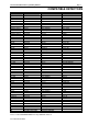
IFS-2600 Installation & Programming Manual Page 5 COMPATIBLE DETECTORS Make System Sensor System Sensor System Sensor System Sensor System Sensor System Sensor System Sensor System Sensor System Sensor System Sensor System Sensor System Sensor System Sensor Model Thermal Thermal Thermal Thermal Thermal Thermal Thermal Smoke Smoke Smoke Thermal Smoke Smoke Type Type A Type A Type B Type B Type B Sealed Type C Type D Photo-Optical Photo-Optical Ionisation Type D Beam Duct Model Number 5451 AUS 51A51 4451
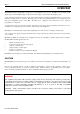
Page 6 IFS-2600 Installation & Programming Manual OVERVIEW IFS-2600 Fire Indicator Panel (FIP) is designed to provide simplicity to the end user. The FIP uses both a liquid crystal display and conventional LED displays for fast and accurate display of system status and changing events. A custom designed membrane keypad is used together with the liquid crystal display and LED indicators to provide fast, efficient and simple modes of operation.
IFS-2600 Installation & Programming Manual Page 7 SPECIFICATION Cabinet Zinc Sealed Steel 1.6mm Powder Coated Hinged Inner Door Hinged Outer Door Outside Dimensions 2608 (8 zones) 2624 (24 zones) 2600 (32 to 64 zones) Battery Box 394mm H x 390mm W x 180mm D* 750mm H x 390mm W x 180mm D* 18U, 28U & 40U Cabinets *Note: the depth quoted is including the door and break glass. The internal cabinet depth not including he door and break glass is 140mm.
Page 8 IFS-2600 Installation & Programming Manual SYSTEM EXPANSION Zones 8 16 24 32 40 48 56 64 Qty 1 1 1 1 1 1 1 1 1 1 1 2 1 1 1 1 3 2 1 1 1 4 2 1 1 1 5 3 1 1 1 6 3 1 1 1 7 4 Hardware Required Main Control Board Main Termination board Power Supply board Main Control board Main Termination board Power Supply board 8 Zone Expansion board 16 Zone Indicator board Main Control board Main Termination board Power Supply board 8 Zone Expansion board 16 Zone Indicator board Main Control board Main Termin
IFS-2600 Installation & Programming Manual Page 9 POWER SUPPLY RATINGS AND SETTINGS INTERNAL 24 VDC (nom) 3.0A MAIN POWER SUPPLY This supply's primary function is to power panel logic and all external operations of the FIP, i.e.: detection circuits, ancillary circuits, etc. This supply meets the requirements of AS4428.5. AC Input Output Current Output Voltage Current Limit Output Ripple 30 VAC +10% - 15% 3.0 AMPS 26.5 VDC 3.0 AMPS 50 mV INTERNAL 27.3V DC 1.
Page 10 IFS-2600 Installation & Programming Manual EXTERNAL 27VDC POWER SUPPLY This supply is used in addition to the internal power supply for large systems. Its primary function is to power any additional ancillary loads of the FIP up to 7 amps. This supply meets the requirements of AS4428.5 Important Notes: When using external power supply, JP1 link on IFS2006E must be fitted to enable external PSU monitoring.
IFS-2600 Installation & Programming Manual Page 11 TECHNICAL DESCRIPTION GENERAL The IFS-2600 in its most basic form comprises of three boards, the main control board, the main termination board and the power supply board. 2 The main control board contains the Microprocessor, EPROM, RAM and E ROM. The main control board also has the liquid crystal display and keypad attached. All of the "delicate" electronics have been placed on this board.
Page 12 IFS-2600 Installation & Programming Manual AZF DESCRIPTION The AZF's on the IFS-2600 are monitored and scanned by custom thick film hybrids. These hybrid IC's significantly reduce the possibility of false alarms and improve product efficiency and reliability. The total Alarm Zone loop resistance is the sum of the end of line resistor (EOLR 4K7) plus all the parallel connected detector loads.
IFS-2600 Installation & Programming Manual Page 13 PRINTER OUTPUT The printer port is designed to be used during testing and commissioning of the panel. The serial printer will report alarms and faults together with the date and time of the event. The printer can also be used during “walk test” mode to produce a history of the test and can also be used to print current programming configuration. A DB9 plug male is provided at the top of the main termination board.
Page 14 IFS-2600 Installation & Programming Manual ALIGNMENT AND ADJUSTMENT PCB2006 POWER SUPPLY BOARD INTERNAL 24VDC (nom) POWER SUPPLY With batteries disconnected and no alarms present, measure voltage across the 0V and MAIN test points on the 2006 power supply board and, if necessary, adjust the multi-turn potentiometer VR2 until voltage is 26.5V 0.05V (26.45V – 26.55V). Current limiting is fixed and field adjustment is not possible. INTERNAL 27.
IFS-2600 Installation & Programming Manual Page 15 ALARM THRESHOLD COMPARATOR TP7 With the panel in the quiescent mode, measure and take note of the INTERNAL 24V DC POWER SUPPLY as above. Measure voltage between system 0V and TP7. Adjust multi-turn potentiometer VR4, and adjust until the voltage is as per the following table. Rail Voltage 20.6 21.0 21.5 22.0 22.5 23.0 23.5 24.0 24.5 25.0 25.5 26.0 26.5 27.0 27.5 27.6 28.0 3.3V Setting 2.833 2.888 2.956 3.025 3.094 3.163 3.231 3.300 3.369 3.438 3.506 3.
Page 16 IFS-2600 Installation & Programming Manual CONFIGURATION JUMPERS IFS2004 - JP3 DEFAULT Holding a short across these pins for 5 seconds during start-up causes the panel to reset to standard factory defaults. The panel will give 4 beeps after reset, to acknowledge default on start-up. IFS2004 - JP4 PROGRAM DISABLE When fitted, jumper between these pins to inhibit program changes. IFS2004 - JP5 CPU RESET With panel operating, a momentary short across these pins will cause a CPU restart.
IFS-2600 Installation & Programming Manual Page 17 PLACING INTO OPERATION Suitably qualified technicians must install the panel. The following check procedures are recommended after every installation and prior to initial power-up. A thorough visual inspection should be made to every aspect of the fire panel. This includes loose wire, metal filings, loose circuit boards, loose cabling, damage in transit etc.
Page 18 IFS-2600 Installation & Programming Manual POWER UP CHECKLIST Ensure batteries are disconnected. Turn mains switch to "on" The "mains on" led should light. Allow 15 seconds for the panel to perform its start up tests. Connect batteries FUNCTIONAL TESTING Primary ac supply voltage: 200 or 220 or 240vac +10% as required Charger output voltage without batteries: 27.
IFS-2600 Installation & Programming Manual Page 19 FAULT RECORD FAULT CORRECTION DATE TESTS SATISFACTORILY COMPLETED. TESTED BY _______________________________ SIGNATURE _______________________________ DATE OF TEST ____________________________ If all faults have been rectified and all tests are completed satisfactorily, the 2600 fire indicator panel is now ready for operation.
Page 20 IFS-2600 Installation & Programming Manual INSTRUCTIONS TO OPERATORS INDICATORS Qty Descriptor Colour Function Illuminates when there is 200/220/240 VAC supply to the panel. Illuminates if the battery fails a battery test. Illuminates if batteries are disconnected >30 seconds. Illuminates if batteries are short circuit >30 seconds. Illuminates if the power supply is outside the manufacturers range. Illuminates if the battery charger is outside the recommended float charge voltage.
IFS-2600 Installation & Programming Manual Page 21 SUGGESTED ALARM PROCEDURE The following is a suggested alarm procedure for use by building fire officers or duty wardens. The fire indicator panel is designed for use by qualified fire fighters and it is strongly recommended that the fire panel not be operated in an emergency situation by anyone other than suitably qualified fire fighters. Do not open fire indicator panel door or press any buttons until fire officers arrives.
Page 22 IFS-2600 Installation & Programming Manual EXT BELL BELL ISOLATE ISOL Depressing the "EXT BELL ISOLATE" key will isolate the bells. The "Ext Bells Isolate" LED will illuminate and the bells will not sound until the bells are de-isolated. Pressing "EXT BELL ISOLATE" a second time will deisolate the bell. WARN SYS ISOLATE WARN SYS ISOL Depressing the "WARN SYS ISOLATE" key will isolate the warning system.
IFS-2600 Installation & Programming Manual WALK TEST MODE Page 23 WALK TEST This function will place the panel into "walk test" mode. Walk test mode is used for the on-site testing of detector zones. This mode cannot be selected if any zone(s) is in alarm. Entry to walk test mode will be acknowledged by three beeps and the LCD will display "WALK TEST MODE".
Page 24 IFS-2600 Installation & Programming Manual ZONE FUNCTIONS Zone functions are those relating specifically to the detection zones. Following is an explanation of their operation and the keystrokes required to perform the function required. ALARM TEST ALARM TEST # ENT The alarm test function momentarily disconnects the detector lines of the zone(s) under test and simulates a detector going into alarm, therefore testing the zone(s) alarm detection capability.
IFS-2600 Installation & Programming Manual FAULT TEST Page 25 FAULT TEST # ENTER The fault test function momentarily disconnects the detection zone(s) under test and simulates the worst-case condition for fault. A resistor load equal to worst case fault is placed on the zone continuously for 5 seconds then the zone is returned back to its normal condition.
Page 26 IFS-2600 Installation & Programming Manual ISOLATE ISOLATE # ENTER The isolate function prevents the transmission of alarms or faults from the zones, to the master alarm facility. ‘#’ in the above key sequence is the zone number. If only one zone is to be isolated, use the appropriate zone number. Alternatively the "ALL" button can be used to simultaneously isolate all zones. To isolate a particular zone or all zones: 1. Press the "ISOLATE" button.
IFS-2600 Installation & Programming Manual Page 27 PROGRAMMING GLOBAL OPTIONS ANCILLARY TRIP 1 2 3 4 LATCHING NON-LATCHING LATCHING NON-LATCHING NORMALLY DE-ENERGISED NORMALLY DE-ENERGISED NORMALLY ENERGISED NORMALLY ENERGISED ALARM VERIFICATION 1 2 3 4 5 DISABLED 2 MINUTES 3 MINUTES 4 MINUTES 5 MINUTES TIME (DD) / (MM) / (YY) (HH) : (MM) ZONE OPTIONS 1 2 3 4 5 6 7 8 9 10 DESCRIPTION INPUT DELAY Standard Latching Standard Latching Non Latching Non Latching Time Delay Time Delay Time Delay Time De
Page 28 IFS-2600 Installation & Programming Manual OUTPUT RELAY OPTIONS Optional Relays can be programmed to simulate: - Isolate Relay ACF Output Brigade Relay #1 Brigade Relay #2 Fault Relay Mains Fail Relay General Alarm Relay Bell Output Door Holder Relay Door Switch Reset Or Can Be Used To: "MAP AND" "MAP OR" “MAP FAULT” “MAP ISOLATE” “MAP ISO/FAULT” Up to 5 Zones in Alarm Up to 5 Zones in Alarm Up to 5 Zones in Fault Up to 5 Zones in Isolate Up to 5 Zones in Isol
IFS-2600 Installation & Programming Manual Page 29 PROGRAM MODE Press the following buttons in order shown to enter programming mode. PREVIOUS → NEXT → → SELECT EXIT → ENTER PROGRAMMING MODE The liquid crystal display will display all messages and prompts required to program the 2600. ONLY the "PREVIOUS","NEXT","SELECT","EXIT" AND "ENTER" keys are used in programming mode. All other keys will give an error beep and are ignored.
Page 30 IFS-2600 Installation & Programming Manual RELAYS TYPE ISOLATE RELAY ANCILLARY OUTPUT (ACF) BRIGADE RELAY #1 BRIGADE RELAY #2 FAULT RELAY MAINS FAIL RELAY GENERAL ALARM RELAY BELL OUTPUT DOOR HOLDER RELAY MAP - AND MAP - OR MAP - FAULT MAP – ISOLATE MAP – ISOLATE / FAULT DOOR SWITCH RESET MAPPING (00)(00)(00)(00)(00) (00)(00)(00)(00)(00) (00)(00)(00)(00)(00) (00)(00)(00)(00)(00) (00)(00)(00)(00)(00) GLOBAL ACF NON-LATCHING ND LATCHING ND NON-LATCHING NE LATCHING NE AVF DISABLED 2 MINUTES 3 MIN
IFS-2600 Installation & Programming Manual Page 31 EXIT PROGRAMMING MODE SAVE YES CHANGES (NO) Use the "NEXT" & "PREVIOUS" keys to scroll through "YES" & "NO". Once the desired option has been highlighted, pressing the "SELECT" button will select it. 2 Highlighting "YES" and pressing "SELECT" will write all changes made to the system memory (E ROM) and the panel will then restart. WARNING!! The above action cause the panel to drop any door holders / air-conditioning if connected.
Page 32 IFS-2600 Installation & Programming Manual Once the desired option has been highlighted, pressing the "SELECT" button will select it. Making a selection or pressing "EXIT" will return to zone selected. Note: The option previously set is displayed in brackets and is the first to be displayed. Previously set options will not be displayed if "ALL" is selected. A function of “BELL” also operates the WARNING SYSTEM.
IFS-2600 Installation & Programming Manual Page 33 RELAY TYPE RELAY #ALL TYPE (GENERAL) Use the "NEXT" & "PREVIOUS" keys to scroll through: ISOLATE ANCILLARY BRIGADE 1 BRIGADE 2 FAULT MAINS FAIL GENERAL BELL DOOR HOLDER MAP -ANDMAP -ORMAP –FAULTMAP –ISOLATEMAP -ISOLATE/FLTDOOR SWITCH RESET Once the desired option has been highlighted, pressing the "SELECT" button will select it. Making a selection or pressing "EXIT" will return to "Relay Selected".
Page 34 IFS-2600 Installation & Programming Manual ACF OUTPUT ACF OUTPUT (NON-LATCH ND) Use the "NEXT" & "PREVIOUS" keys to scroll through: LATCHING ND NON-LATCH NE LATCHING NE Note: The option previously set is displayed in brackets and is the first to be displayed. ND = Normally De-energised i.e.: Output is not energised until an alarm occurs. NE = Normally energised i.e.: Output is energised and then is de-energised once an alarm occurs.
IFS-2600 Installation & Programming Manual Page 35 Then relay #1 would be set as MAP OR with its mapping as (09) 00 00 00 00, relay #2 would be set as MAP OR with it’s mapping set as (10) 00 00 00 00 and so on all the way up to relay #64. Note: In example 2, zone number 64 is reached and there are still more relays to go. (I.e. we are only at relay #56) the programming stops at this point and any relays not yet programmed will be left in their previous programmed mode and are unaffected by this function.
Page 36 IFS-2600 Installation & Programming Manual APPENDIX A DESCRIPTION OF ALARM ZONE TYPES Different zone types can be selected using the programming mode.
IFS-2600 Installation & Programming Manual Page 37 TIME DELAY AZF The time delay AZF zone can be preset to any one of 6 time delays in the initial setup. This type of zone is used for AS1668 smoke detection zones. Zone timing etc is as per AS1668-1991. Example: Timer #1 = 60 seconds Once the first alarm is received, the alarm LED is turned on steady; this indicates "PARTIAL ALARM" condition. The detector is then reset (by removing its power for 0.
Page 38 IFS-2600 Installation & Programming Manual APPENDIX B ZONE OUTPUT CONFIGURATIONS Once a zone has alarmed, its output functions as programmed to one of the following output types.
IFS-2600 Installation & Programming Manual Page 39 APPENDIX C ALARM VERIFICATION FACILITY (AVF) Alarm verification (AVF) is a facility used to minimise false alarms. AVF only applies to the zones programmed for the AVF function. GLOBAL PROGRAMMABLE OPTIONS AVF TIMEOUT Disabled 2 Minutes 3 Minutes 4 Minutes 5 Minutes Operation is as follows: If a zone is programmed as AVF and it registers an alarm, no alarm functions are performed, if it is the first AVF zone in alarm.
Page 40 IFS-2600 Installation & Programming Manual APPENDIX D ANCILLARY TRIP (ACF) The ancillary trip is used for the shutting down of air conditioning systems etc. in the event of a fire. GLOBAL PROGRAMMABLE OPTIONS ANCILLARY TRIP (ACF) NON-LATCHING ND LATCHING ND NON-LATCHING NE LATCHING NE The ancillary trip can be programmed as latching or non- latching depending on the application. It call also be programmed as normally energised or normally de-energised.
IFS-2600 Installation & Programming Manual Page 41 APPENDIX E RELAY OUTPUT MAPPING A total of 64 expansion relays can be fitted to the IFS-2600.
Page 42 IFS-2600 Installation & Programming Manual FAULT/ISOLATE MAPPING FAULT/ISOLATE MAPPING works the same as OR mapping of alarm except it relates to the fault/isolate flag on each zone instead of the alarm flag. This function will cause the relay to operate if any one of up to five (5) zones go into fault/put in isolate. If the relay map options are set as "01" "02" "03" "00" "00", then zones 1 or 2 or 3 going into fault/(or are manually put in isolate) will cause the relay to operate.
IFS-2600 Installation & Programming Manual Page 43 APPENDIX F GLOSSARY OF TERMS AS-4428.1 Australian standard for; Automatic Fire Detection and Alarm Systems Control and Indicating Equipment. AS-4428.1 Australian standard for; Automatic Fire Detection and Alarm Systems Power Supply Units. AS-1670 Australian standard for; Automatic Fire Detection and Alarm Systems System Design Installation and Commissioning. AS-1668.
Page 44 IFS-2600 Installation & Programming Manual APPENDIX G SUMMARY OF TERMINATIONS AND CAUTIONS MCP LOOP Used for the looping of the manual call point to a particular zone chosen for indication. This is achieved by wiring from the zone, to the MCP, to the MCP loop then out to the field with the EOL across the last detector. The MCP is the first device on the circuit and both fault and alarm conditions will be indicated.
IFS-2600 Installation & Programming Manual Page 45 BATTERY The 24V batteries are connected at these terminals. damage to the equipment. Reverse polarity will cause serious and permanent DOOR HOLDER AC INPUT Terminate the door holder AC transformer at these terminals. 24 VAC is the only acceptable power source at this point. DO NOT connect 240VAC at this point. OUTPUT RELAYS STANDBY (N) Normally energised, drops out when power supply (or battery supply) is below specified voltage.
Page 46 IFS-2600 Installation & Programming Manual APPENDIX H IFS-2600 PROGRAMMED OPTIONS Global System Parameters Latch ND Date: Non-Latch ND / / Latch NE Non-Latch NE ACF Output Disabled 2 min 3 min 4 min Alarm Verification (AVF) Notes: Programmed by Place an "X" in the appropriate box P/N 10069 ECN08-0066 = Default 5 min
IFS-2600 Installation & Programming Manual Page 47 ZONE TYPE PROGRAMMING 1 2 3 AZF No.
Page 48 1 2 3 AZF No.
IFS-2600 Installation & Programming Manual ZONE OUTPUT PROGRAMMING AZF No.
Page 50 AZF No.
IFS-2600 Installation & Programming Manual Page 51 RELAY OUTPUT MAPPING Date: / / MAPPING RLY ISO ACF BR1 BR2 FLT MAINS FAIL GEN BELL D/H AND OR FLT 1 2 3 4 5 6 7 8 9 10 11 12 13 14 15 16 17 18 19 20 21 22 23 24 25 26 27 28 29 30 31 32 Place an "X" in the appropriate box P/N 10069 ECN08-0066 = Default ISO ISO/ FLT DOOR RESET
Page 52 IFS-2600 Installation & Programming Manual MAPPING RLY ISO ACF BR1 33 34 35 36 37 38 39 40 41 42 43 44 45 46 47 48 49 50 51 52 53 54 55 56 57 58 59 60 61 62 63 64 P/N 10069 ECN08-0066 BR2 FLT MAINS FAIL GEN BELL D/H AND OR FLT ISO ISO/ FLT DOOR RESET
IFS-2600 Installation & Programming Manual Page 53 APPENDIX I TECHNICAL DRAWINGS MAIN KEYPAD AND DISPLAY EXPANSION DISPLAY P/N 10069 ECN08-0066
Page 54 IFS-2600 Installation & Programming Manual Block Connection Diagram 1 2 3 4 4 CORE CABLE TX, CTS, GND DB-9 FEMALE SERIAL PRINTER A A OUTPUTS PCB1125 MAIN TERMINATION BOARD MAIN PROCESSOR BOARD IFS PCB2005 CABLE C32 IFS PCB2004 ZONE DISPLAYS 1-8 BELL/ACF POWER SUPPLY BOARD PCB2006 ZONE INPUTS 1-8 MAX 120M CABLE C3 CABLE C5 LAPTOP 3 CORE CABLE RX, TX, GND OUT CABLE C1 P/N 130 16 ZONE DISP PCB816 ZONE INPUTS 9-16 B ZONE IN OUT RELAY EXP PCB804 BOARD IFS803 4 CORE CABLE 8 R
IFS-2600 Installation & Programming Manual Page 55 System Sensor Conventional Detector Connection Diagram 1 2 3 DET A A DET B DET B + 3 4 5 +R +D -D 1 TO PANEL A 4 RIP 4 5 4 RIP 5 1 +R +D -D 1 3 3 4K7 EOL 2 - 2 BASE B401 2 BASE B401 CONVENTIONAL DETECTOR CONNECTION DIAGRAM B BASE A PROBE A + PROBE B 4 5 4 5 SEALED PROBE 1 TO PANEL B BASE B 3 SEALED PROBE 1 3 4K7 EOL 2 - 2 BASE B401R BASE B401R SEALED DETECTOR CONNECTION DIAGRAM ( NORMAL HEAD NOT CONNE
Page 56 IFS-2600 Installation & Programming Manual Hochiki Conventional Detector Connection Diagram 1 2 DET A A DET B 3 + 1 +R +D -D 5 7 3 3 2 4 6 4 DET C RIP 2 TO PANEL 3 1 4 1 5 7 RIP 2 4 6 +R +D -D 5 7 6 A 4K7 EOL CONNECTION FOR STANDARD DETECTORS AND BASES B B DET A DET B DET C + RIP BLUE L TO PANEL RED S RIP +R +D -D C WHITE - L S C L S +R +D -D C 4K7 EOL CONNECTION FOR DFG-60BLKJ SEALED DETECTOR C C +R Current limited 10 mA 470R +R +D Not cu
IFS-2600 Installation & Programming Manual Page 57 Ancillary Connection Diagram 1 2 3 4 1 2 3 4 NOTE: PCB1125 may be omitted if the ancillary device is high impedance or contains an inbuilt reverse protection diode. A + + IN - LOAD + D2 D1 R1 - OUT - In this case a 4K7 EOL must be fitted to the last device on the circuit.
Page 58 IFS-2600 Installation & Programming Manual ASE Connection Diagram 1 2 3 4 A N IFS2600 B N FAULT BRIGADE 2 BRIGADE 1 STANDBY A N/O N/C COM AUX ISOLATE N AC-FAIL PCB2004 C N/O N/C COM No. Revision - revise on CAD. Do not amend by hand Eng. 1 P/N 10069 ECN08-0066 App.
IFS-2600 Installation & Programming Manual Page 59 Auto Changeover Dual Sounder Connection Diagram 1 2 3 4 A A NOTE: NOTE: Maximum capacity is 10 sounders or 4 strobes INSTALL LINK JP1 FOR AUTO CHANGEOVER FROM ALERT TO EVAC TERM B TERM A +24 0V AL EVAC FAULT N/O NC COM NO NC COM NO 0V IFS958 RELAY BOARD +24V IFS2600 TERMINATION PCB2004 B FAULT COM MONITORED DRIVER BOARD IFS 993 B ALERT STROBE (AMBER) EVAC STROBE (RED) WARN +24 ACF +24 BELL N/O AUX C 0V +24V RED 0V BL
Page 60 IFS-2600 Installation & Programming Manual Auto Change Over Dual Sounder Connection Diagram 1 2 3 4 A A NOTE: NOTE: Maximum capacity is 10 sounders or 4 strobes REMOVE LINK JP1 FOR MANUAL CHANGEOVER FROM ALERT TO EVAC IFS2600 TERMINATION PCB2004 TERM B TERM A +24 0V AL EVAC NC COM NO NC COM 0V NO +24V WARN BELL AUX ACF +24 0V IFS958 RELAY BOARD ALERT ACTIVATION +24 FAULT N/O N/O B FAULT COM MONITORED DRIVER BOARD IFS 993 B ALERT STROBE (AMBER) EVAC STROBE (RED)
IFS-2600 Installation & Programming Manual Page 61 MIMIC Connection Diagram 1 2 3 PCB812 4 PCB812 PCB812 A A ZONES 1-8 IFS2600 TERMINATION BOARD ZONES 9-16 ZONES 17-24 PCB810 FITTED WITH IFS2600 MIMIC DRIVER WARN +24 +24 0V B 33-40 1-8 41-48 9-16 49-56 17-24 57-64 25-32 0V 0V DATA +24 CLK 0V +24 +24 0V AUX ACF B BELL N/O TP 0V Max 120 Meters 4/0.
Page 62 IFS-2600 Installation & Programming Manual Single Fan Connection Diagram 1 2 3 4 FIRE PANEL FIELD WIRING A A FAN TERMINATION BOARD AUX POWER AUX +24 +24 AUX 0V 0V +24 COMMON +VE START STOP START CONTROL FAN START RELAY START1 STOP STOP1 RUN FAN RUNNING STOP INDICATION FAN STOPPED AND POWER AVAILABLE B B FLT FAN FAULT OR NO POWER AVAILABLE FAN STOP RELAY RIBBON CABLE PCB1128 C FAN 1 C RUN STOP FAULT * NOTE AUTO OFF ON THE MECHANICAL SERVICES BOARD MUST BE CONFI
IFS-2600 Installation & Programming Manual Page 63 Dual Fan Connection Diagram 1 2 3 4 FIRE PANEL FIELD WIRING A A FAN TERMINATION BOARD AUX POWER AUX +24 +24 AUX 0V 0V +24 COMMON +VE START STOP START CONTROL FAN 1 START RELAY START1 STOP STOP1 RUN START2 STOP FAN 1 FAN RUNNING INDICATION FAN STOPPED AND POWER AVAILABLE B B STOP2 FLT FAN FAULT OR NO POWER AVAILABLE FAN 1 STOP RELAY +24 COMMON +VE START START STOP CONTROL FAN 2 START RELAY STOP FAN 2 PCB1102 RUN FAN R
Page 64 IFS-2600 Installation & Programming Manual Exhaust Fan Connection Diagram 1 2 3 4 FIRE PANEL FIELD WIRING FAN TERMINATION BOARD A A AUX POWER AUX +24 +24 AUX 0V 0V +24 COMMON +VE START STOP START CONTROL START1 FAN STOP RELAY (MAPPED TO ACF FOR GENERAL OR ZONED) STOP1 STOP RUN FAN RUNNING STOP INDICATION FAN STOPPED AND POWER AVAILABLE FLT FAN FAULT OR NO POWER AVAILABLE B B PCB1128 * NOTE RIBBON CABLE EITHER THE MAPPING ABOVE MAY BE USED TO STOP THE EXHAUST FAN OR TH
IFS-2600 Installation & Programming Manual Page 65 Supply Fan Connection Diagram 1 2 3 4 FIRE PANEL FIELD WIRING FAN TERMINATION BOARD A A AUX POWER AUX +24 +24 AUX 0V 0V +24 COMMON +VE START STOP START CONTROL START1 FAN START RELAY (MAPPED TO ACF FOR GENERAL OR ZONED) STOP1 STOP RUN FAN RUNNING STOP INDICATION FAN STOPPED AND POWER AVAILABLE FLT FAN FAULT OR NO POWER AVAILABLE FAN STOP RELAY (MAPPED TO AIR INTAKE SMOKE DETECTOR) B B PCB1128 * NOTE RIBBON CABLE EITHER THE M
Page 66 IFS-2600 Installation & Programming Manual Smoke Spill Fan Connection Diagram 1 2 3 4 FIRE PANEL FIELD WIRING FAN TERMINATION BOARD A A AUX POWER AUX +24 +24 AUX 0V 0V +24 COMMON +VE START STOP START CONTROL START1 FAN START RELAY (MAPPED TO ACF FOR GENERAL OR ZONED) STOP1 STOP RUN FAN RUNNING STOP INDICATION FAN STOPPED AND POWER AVAILABLE FLT B FAN FAULT OR NO POWER AVAILABLE B * NOTE EITHER THE MAPPING ABOVE MAY BE USED TO START THE SSF OR THE GENERAL ACF TRIP BELOW,
IFS-2600 Installation & Programming Manual Page 67 10W EVAC Connection Diagram 2 3 4 VOL 1 A COM LINE + +24 GND SOUND JP1 JP2 BGM + BGM - PA - 0V PA+ PTT ALERT IN BGM EN EVAC IN ALARM EVAC OUT FAULT +24 0V ALERT OUT +24 +24V COM WARN IFS2600 TERMINATION BOARD AUX A 10W EVAC PCB 908 PA FRONT PANEL EVAC CONTROL 0V EXTERNAL POWER MONITOR JP1 B 4K7 5% EOL SPEAKERS WITH 47K 5% 100V LINE TRANSFORMERS AND ISOLATION CAPACITORS LINK JP1 WHITE RED 0V +24V BATT REMOTE INPU
Page 68 IFS-2600 Installation & Programming Manual 10W EVAC Slave Connection Diagram 2 3 4 VOL 1 A COM LINE + +24 GND SOUND JP1 JP2 BGM + BGM - PA - 0V PA+ PTT ALERT IN BGM EN EVAC IN ALARM EVAC OUT FAULT +24 0V ALERT OUT +24 +24V COM WARN IFS2600 TERMINATION BOARD AUX A 10W EVAC PCB 908 PA FRONT PANEL EVAC CONTROL 0V EXTERNAL POWER MONITOR JP1 B 4K7 5% EOL SPEAKERS WITH 47K 5% 100V LINE TRANSFORMERS AND ISOLATION CAPACITORS LINK JP1 CONNECT TO FAULT OUT FROM SLAVE
IFS-2600 Installation & Programming Manual Page 69 30W EVAC Connection Diagram 2 3 4 VOL 1 A COM LINE + +24 GND SOUND JP1 JP2 BGM + BGM - PA - 0V PA+ PTT ALERT IN BGM EN EVAC IN ALARM EVAC OUT 0V FAULT +24 +24V COM WARN +24 AUX IFS2600 TERMINATION BOARD ALERT OUT A 30W EVAC PCB 908 PA FRONT PANEL EVAC CONTROL 0V EXTERNAL POWER MONITOR JP1 B 4K7 5% EOL SPEAKERS WITH 47K 5% 100V LINE TRANSFORMERS AND ISOLATION CAPACITORS LINK JP1 WHITE RED 0V +24V BATT REMOTE INPU
Page 70 IFS-2600 Installation & Programming Manual 30W EVAC Slave Connection Diagram 2 3 4 VOL 1 COM LINE + GND SOUND JP1 JP2 BGM + BGM - PA - 0V PA+ PTT ALERT IN BGM EN EVAC IN ALARM EVAC OUT FAULT 0V ALERT OUT +24 +24V COM WARN +24 AUX IFS2600 TERMINATION BOARD A +24 A 30W EVAC PCB 908 PA FRONT PANEL EVAC CONTROL 0V EXTERNAL POWER MONITOR JP1 B 4K7 5% EOL SPEAKERS WITH 47K 5% 100V LINE TRANSFORMERS AND ISOLATION CAPACITORS LINK JP1 CONNECT TO FAULT OUT FROM SLAVE
IFS-2600 Installation & Programming Manual Page 71 50W EVAC Connection Diagram 1 2 AUDIO TRANSFORMER A 3 0 60 2 30 4 20 6 10 8 0 4 A PA GAIN BAT OV JP1 JP2 +24 BAT BGM - BGM + PA - PA+ GND PTT ALERT EVAC BGM EN ALARM EVAC OUT ALERT OUT FAULT +24 COM EXTERNAL POWER MONITOR JP1 0V +24V BATT REMOTE INPUT 0V +24V REMOTE OUTPUT 0V +24V AC INPUT LINK JP1 TO SLAVE TWO AMPLIFIERS TOGETHER, REMOVE THE IFS903 BOARD FROM THE SLAVE AMPLIFIER AND CONNECT JP1 ON THE MASTER TO JP
Page 72 IFS-2600 Installation & Programming Manual 50W EVAC Slave Connection Diagram 1 2 AUDIO TRANSFORMER A 3 0 60 2 30 4 20 6 10 8 0 4 A PA GAIN SOUND MAIN AUX +24 BAT OV JP1 JP2 +24 BAT BGM - BGM + PA - PA+ GND PTT ALERT EVAC BGM EN ALARM EVAC OUT ALERT OUT +24 COM EXTERNAL POWER MONITOR JP1 0V +24V BATT REMOTE INPUT 0V +24V REMOTE OUTPUT 0V +24V AC INPUT LINK JP1 FAULT 0V B TO SLAVE TWO AMPLIFIERS TOGETHER, REMOVE THE IFS903 BOARD FROM THE SLAVE AMPLIFIER
Notes
Notes
New South Wales (Head Office) 7 Columbia Court Baulkham Hills NSW 2153 Queensland 24 Potts Street East Brisbane, QLD 4169 Victoria 32 Lambert Street Richmond, VIC 3121 ph +61 (02 9899-4155 fax +61 (0)2 9899-4156 ph +61 (0)7 3391 5777 fax +61 (0)7 3391 5800 ph +61 (0)3 9421 5552 fax +61 (0)3 9421 5553 Western Australia Unit 4, 283 Camboon Road Malaga WA 6090 New Zealand 264 Mt Eden Road Auckland ph +61 (0)8 9270 6555 fax +61 (0)8 9270 6556 ph +64 (0)9 623 5275 fax +64 (0)9 623 5060