
Submittal Sheet


S05, S10, S20 SERIES SPRING RETURN DIRECT COUPLED ACTUATORS
63-2607—08 2
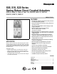
ORDERING INFORMATION
When purchasing replacement and modernization products from your TRADELINE® wholesaler or distributor, refer to the
TRADELINE® Catalog or price sheets for complete ordering number.
If you have additional questions, need further information, or would like to comment on our products or services, please write or
phone:
1. Your local Honeywell Automation and Control Products Sales Office (check white pages of your phone directory).
2. Honeywell Customer Care
1885 Douglas Drive North
Minneapolis, Minnesota 55422-4386
In Canada—Honeywell Limited/Honeywell Limitée, 35 Dynamic Drive, Toronto, Ontario M1V 4Z9.
International Sales and Service Offices in all principal cities of the world. Manufacturing in Australia, Canada, Finland, France,
Germany, Japan, Mexico, Netherlands, Spain, Taiwan, United Kingdom, U.S.A.
SPECIFICATIONS
Models: See Tables 2 and 3.
NOTE: This document also covers the MS7110K and
MS7106K.
Dimensions: See Fig. 1.
Device Weight: 7 lb (3.2 kg).
Temperature Ratings:
Ambient: -40°F to 140°F (-40°C to 60°C).
Shipping and Storage: -40°F to 158°F (-40°C to 70°C).
Humidity Ratings: 5% to 95% RH noncondensing.
Electrical Connections:
Field wiring 14 to 22 AWG (2.0 to 0.344 mm sq) to screw
terminals, located under the removable access cover.
Electrical Ratings: See Table 1.
End Switches (Two SPDT):
Settings (fixed): 7° nominal stroke, 85° nominal stroke.
Ratings (maximum load):
Low-Voltage Models: 250 Vac, 5A resistive, 3A inductive.
Line-Voltage Models: 250 Vac, 5A resistive.
Mounting: Self-centering shaft adapter (shaft coupling).
Round Damper Shafts: 0.375 to 1.06 in. (10 to 27 mm).
Square Damper Shafts: 1/2 to 3/4 in. (13 to 19 mm).
Actuator can be mounted with shaft in any position.
NOTE: For 175 lb-in. (20 N•m) models: 3/4 in. or greater
shaft diameter recommended.
Minimum Damper Shaft Length: 1 in. (25 mm); 3 in.
(76 mm) recommended.
Timing (At Rated Torque and Voltage):
Drive Open (typical):
Floating, Modulating Models: 90 seconds.
Floating, Modulating Models: 60 seconds.
Two-Position Models: 45 seconds ±5 seconds.
Spring Close: 20 seconds typical.
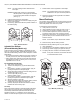
Fig. 1. Dimensional drawing of actuator in in. (mm).
Table 1. Electrical Ratings*.
* Floating/Modulating 60 sec models
88 lb-in. (10 N•m) 18 VA Driving
175 lb-in. (20 N•m) 22 VA Driving
24 VAC +- 20%
9-3/4
(247)
1-9/16
(40)
2-1/2
(64)
MIN.
3 (76)
MIN.
3 (76)
MIN.
FROM
SHAFT
END
6-1/8
(156)
1-9/16
(40)
1-9/16
(40)
3-15/16 (100)
2-15/16 (75)
1/4 (6)
M20952
Model(s)
Power Input Power Consumption (VA)
Voltage Frequency
44 lb-in. (5 N•m) 88 lb-in. (10 N•m) 175 lb-in. (20 N•m)
Driving Holding Driving Holding Driving Holding
Floating, Modulating 24 Vac ±20% (Class 2), 24 Vdc 50/60 Hz. 13 5 14 5 16 5
Two-Position, Low-voltage 24 Vac ±20% (Class 2), 24 Vdc 50/60 Hz. 25 8 30 8 40 8
Two-Position, Line-voltage 100-250 Vac 50/60 Hz. 45 13 45 13 60 13