
Install Instructions


MP909E,H PNEUMATIC DAMPER ACTUATORS
External Mounting
OFFSET CRANKARM MOUNTING
1.
Obtain one 14004667-001 Offset Crankarm (Fig. 1).
2.
Remove standard crankarm (Fig. 1A) from actuator and
install offset crankarm (Fig. 1B).
3.
Mount actuator and secure offset crankarm to drive axle
as covered in External Mounting Section.
ACTUATOR SHAFT EXTENSION MOUNTING
1.
Obtain the following additional parts for shaft extension:
• One CCT2718 3/8-16 Threaded Rod.
• One CCT2725 3/8-16 Rod Coupling.
• Two CCT2361 3/8-16 Hex Nuts.
2.
Remove clevis pin, washer, and clip (Fig. 9).
3.
Disconnect actuator pushrod from crankarm, and
unscrew actuator pushrod from actuator shaft.
4.
Remove two clevis pins, washers, and clips.
5.
Disconnect actuator from faceplate (Fig. 12).
NOTE: For MP909H, unhook feedback spring.
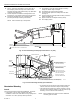
6.
Install mounting bracket using four mounting screws
provided (Fig. 15).
NOTES:
• Location should allow use of straight shaft extension.
• Maximum recommended distance between damper
axle and mounting bracket faceplate is 41 in.
(1041 mm).
• Use minimum distance practical for the installation.
7.
Install actuator to faceplate using the two clevis pins,
washers, and clips from Step 4. See Fig. 16.
NOTE: For MP909H, rehook feedback spring.
8.
For offset shaft installation, bend CCT2718 Threaded
Rod as required. Use 45-degree bends with a maximum
of 3 in. (76.2 mm) offset.
9.
Cut threaded rod 5 in. (127 mm) shorter than faceplate
to damper axle distance as determined in Step 6.
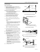
10.
Assemble threaded rod, pushrod, coupling, and nuts to
form actuator shaft extension (Fig. 17).
11.
Adjust threaded rod length for a 1/8 in. (3.2 mm) clinch
at damper closure:
a. Rotate damper axle to closed damper position.
b. If linkage is normally open, pressurize actuator to
fully extended position.
c. Adjust actuator pushrod to obtain 1/8 in. (3.2 mm)
misalignment in pushrod to crankarm clevis pin hole
(Fig. 18).
d. If linkage is normally open, remove pressure to
actuator. If linkage is normally closed, pressurize to
stroke actuator at least 1/8 in. (3.2 mm).
e. Align pushrod and crankarm clevis pin holes and
insert clevis pin.
f. Fasten clevis pin using washer and clip from Step 2.
g. Tighten hex nuts on actuator shaft and threaded rod
(Fig. 17) to lock rod in place.
12.
Go to Piping section.
C2220
MOUNTING
BRACKET
FACEPLATE
DAMPER AXLE
MOUNTING SCREWS
MOUNTING
SURFACE
41 IN. (1041 MM)
MAXIMUM
Fig. 15. Mounting Bracket Installation.
USE THESE HOLES IF FACEPLATE TO DAMPER
IS LESS THAN 15 INCHES. (PINS IN AXIS
PARALLEL TO DAMPER AXLE)
USE THESE HOLES IF FACEPLATE TO DAMPER
IS EQUAL TO OR GREATER THAN 15 INCHES.
(PINS IN AXIS PERPENDICULAR TO DAMPER AXLE)
C2221
Fig. 16. Faceplate Installation.
ACTUATOR PUSHROD
3/8-16 THREADED ROD CCT2718
ACTUATOR SHAFT
ACTUATOR
3/8-16 HEX NUTS CCT2361
3/8-16 ROD COUPLING CCT2725
3/8-16 HEX NUT (FURNISHED WITH ACTUATOR)
1
1 1
1
3/8-IN. (9.5mm) MINIMUM THREAD ENGAGEMENT.
C2239
Fig. 17. Assembling Actuator Shaft Extension.
CRANKARM
HOLE IN
CRANKARM
HOLE IN
PUSHROD
ACTUATOR
PUSHROD
ACTUATOR
1
1
1/8-INCH (3 mm) HOLE MISALIGNMENT OR CLINCH (CLINCH
EQUALS ONE-HALF OF 1/4-INCH (6 mm) DIAMETER HOLES).
C2240
Fig. 18. Threaded Rod Installation.
7 95-7366—2