
Install Instructions


MP909E,H PNEUMATIC DAMPER ACTUATORS
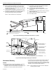
8-7/8 (225)
1 (25)
4-1/2
(114)
2-1/2
(64)
5 (127)
6-3/4
(171)
13-5/8 (352)
MP909E,H
M17465
1
1
DOTTED LINES APPLY TO MP909H ONLY.
Fig. 5. 14002906-001 Bracket Template (Use “B” Holes).
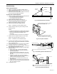
UNFOLD TEMPLATE AND REMOVE PAPER BACKING FROM TAPE.
DETERMINE DAMPER DRIVE AXLE DIRECTION FROM NORMAL POSITION.
INSTALL TEMPLATE WITH APPROPRIATE AXLE HOLE ON TEMPLATE
OVER DAMPER DRIVE AXLE. ARROW SURROUNDING HOLE SHOULD MATCH
ROTATION DETERMINED IN STEP 2.
PRESS TEMPLATE AGAINST DUCT SO THAT IT ADHERES.
PUNCH MOUNTING HOLES.
SCREW MOUNTING BRACKET, WITH ACTUATOR, FIRMLY TO DUCT.
SECURE LINKAGE TO ACTUATOR AND DAMPER DRIVE AXLE.
1.
2.
3.
4.
5.
6.
7.
TEMPLATE
DAMPER SHAFT
M16526
M10435
Fig. 6. External Mounting with Angle Bracket.
Fig. 4. MP909E and H Dimensions in in. (mm) with Angle Bracket.
TRUNNION BRACKET MOUNTING
1.
See Fig. 7 for mounting dimensions.
2.
Check faceplate position and adjust if necessary (Fig. 8).
3.
Determine damper drive axle direction of rotation from
the normal position (normally open or normally closed).
4.
Rotate damper drive axle to normal position. (Position
with 0 psi to actuator).
5.
Install actuator with appropriate shaft hole (Fig. 9) on
mounting bracket over damper axle. Arrow on bracket
surrounding hole should match rotation determined in
Step 3.
6.
Position bracket.
7.
Secure mounting bracket. Use four of the 10 holes
available in bracket and drill screws provided.
8.
To provide close-off force, use a squeeze bulb and
stroke the actuator:
a. For normally open dampers, fully extend actuator
shaft, then retract 1/8 in. (3 mm).
b. For normally closed dampers, extend actuator shaft
1/8 in. (3 mm).
9.
Secure crankarm to damper drive axle.
IMPORTANT
See Fig. 10 for proper crankarm bolt tightening.
10.
Go to Piping section.
3 95-7366—2