
Specification


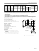


Table Of Contents

L8148A,E,J AQUASTAT® RELAYS
60-2278—9 4
Fig. 2. Internal view of L8148A Aquasta® Relay.
Fig. 3. Internal view of L8148E Aquastat® Relay.
INSTALLATION
When Installing this Product…
1. Read these instructions carefully. Failure to follow them
could damage the product or cause a hazardous
condition.
2. Check the ratings given in the instructions and on the
product to make sure the product is suitable for your
application.
3. Installer must be a trained, experienced service
technician.
4. After installation is complete, check out product
operation as provided in these instructions.
WARNING
Explosion Hazard.
Can cause severe injury, death or property
damage.
This product is intended for use only in systems with a
pressure relief valve.
WARNING
Electrical Shock Hazard.
Can cause severe injury, death or equipment
damage.
1. Disconnect power supply before beginning
installation to prevent electrical shock or equipment
damage.
2. Never apply a jumper across (or short) terminals
B1, B2, or B3. This burns out the transformer.
Mounting (Standard Models)
Boilers have tappings to allow immersion well (which must be
ordered separately) to be mounted horizontally so boiler water
of average temperature can circulate freely around the well.
1. Turn off all power and drain the boiler.
2. If no tapping is provided, prepare one properly sized
and threaded, and locate near the top of the boiler.
3. Coat the well threads sparingly with pipe dope, install
the well in the boiler tapping, and tighten securely.
NOTE: Do not attempt to tighten by using the case as
a handle.
4. Refill the boiler and check for water leakage.
5. Increase sensitivity of the bulb by coating with a good
heat-conductive compound. When used, coat the bulb
completely.
6. Insert the bulb element into the well until it bottoms. If
necessary, slightly bend the tube inside the case to hold
the bulb against the bottom of the well.
NOTE: Some models have a tubing length adjustable to 3 in.
(76 mm). In these models, pull out extra tubing from
inside the case, if needed.
7. Center the loop of excess tubing in front of the
immersion well so it cannot touch any electrical parts.
M8926
VOLTAGE
BARRIER
TRANSFORMER
SWITCHING
RELAY
HIGH
LIMIT
DIAL
M8927
TRANSFORMER
SWITCHING
RELAY
HIGH
LIMIT
DIAL
GROUNDING SCREW