
Datasheet


2 Honeywell MICRO SWITCH Division For application help, call 1-800-537-6945
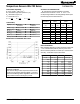
PLATINUM RTDs Temperature Sensors HEL-700 Series
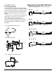
ELECTRICAL INTERFACING
Fig. 1 illustrates the most common method of measur-
ing an RTD. As R
T
increases or decreases with tempera-
ture, Vo increases or decreases. An op-amp is used to
observe Vo. Lead wire resistance, L1 and L2, add to the
RTD leg of the bridge and may affect the temperature
reading.
Fig. 2 is a simple circuit that provides a voltage output
linear to within 0.1% or a ±0.3°C (0.5
°F) error over a
range of -40°C to +150°C (-40°F to +302°F).
Fig. 3 illustrates one way to detect one particular
temperature, if required in an application. The potentiom-
eter may be adjusted to correspond to the desired
temperature.
MOUNTING DIMENSIONS (for reference only) mm/in
HEL-705
HEL-707
HEL-711, HEL-712
HEL-716, HEL-717
4,75
0.08
2,18
0.19
305,0
12.0
Teflon
0.08
6,35
0.25
2,18
305,0
12.0
Fiberglass
Teflon or Fiberglass
2,80
0.11
15,24
0.60
305,0
12.0
3,18
0.12
15,24
0.60
Teflon or Fiberglass
305,0
12.0
Fig. 3: Adjustable Point (Comparator) Interface
Fig. 2: Linear Output Voltage
1K
10K10K10K10K10K10K10K10K
10K10K10K10K10K10K10K10K
V
R
=IV
1K
9K
-Vs
-
+Vs
+
+10V
10K10K10K10K10K10K10K10K
10K10K10K10K10K10K10K10K
R
T
-Vs
-
+
+Vs
T
Vo=.001R
R
T
2K
2K
Vs=5V
-
+
Vo
2K
5K
2K
Fig. 1: Wheatstone Bridge 2-Wire Interface
L
1
L
2
R
T
R
3
R
2
R
1
V
o
+Vs