
User Manual


SYSTEM DESCRIPTION AND INSTALLATION MANUAL
HS--600 High Speed Data System
23--20--31
30 May 2002
Use or disclosure of information on this page is subject to the restrictions in the proprietary notice of this document.
Page 3--4
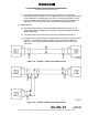
Figure 3-4. Shield Grounding Example for Rack Mount Connectors
(4) Power/Signal Grounds
(a) All dc power grounds are tied together; all ac power grounds are tied together; all
signal grounds are tied together; and all lighting grounds are tied together. DC
power, ac power, signal and light ground groups are then tied together at a single
point and connected to the airframe. Figure 3-5 shows this aircraft grounding
method.
NOTE: It is very important this grounding technique be adhered to. Do not tie
the various ground wires to multiple aircraft frame points and depend on
the aircraft structure to supply a low impedance path for the individual
grounds. Only chassis grounds and shield grounds are grounded at
multiple points in the aircraft.