
Assembly Instructions 1


Assembly Instructions 2/8
I
Figure 2
H
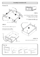
STEP 1
Place Top (A), Base (C), Front Rail (E),
Back Rail (F) and Side Panels (H), (I)
on a soft cloth.
Insert Cam Lock Screws into
pre-drilled holes in Top (A),
Front Rail (E), Back Rail (F) and
Side Panels (H), (I), then tighten.
(See Figure 1)
Attach Magnets to Front Rail (E)
by inserting Wood Screws (short)
into pre-drilled holes, then tighten.
(See Figure 2)
A
C
Cam Lock Screw
E
F
Figure 1
Cam Lock Screw
Magnet
Wood Screw (short)
Cam Lock Screw
IMPORTANT
Use a soft cloth between these parts and the floor.
Do not use power tools above 8 volts to assemble.
Make sure unit is level before tightening these screws.
Do not tighten all the bolts until each part is properly assembled.
The unit must be level to work properly. Use the included adjustable levelers to level.
Keep Hex Wrench as the bolts may need to be tightened in the future.