Item #1003 236 538 Model #AM613A-BN USE AND CARE GUIDE GLENMEADOW 84 IN. CEILING FAN Questions, problems, missing parts? Before returning to the store, call Home Decorators Collection Customer Service 8 a.m. - 7 p.m., EST, Monday-Friday, 9 a.m. - 6 p.m., EST Saturday 1-800-986-3460 HOMEDEPOT.COM/HOMEDECORATORS Visual instruction of how to install this fan: Visit www.homedepot.
Table of Contents Table of Contents .......................................................... 2 Operation ......................................................................16 Preparing the Transmitter ......................................................16 Learning Process ................................................................... 16 Operating Your Fan and Remote Control ............................... 18 Warm/Cool Weather Operating Instructions ...........................
Safety Information 1. To reduce the risk of electric shock, ensure electricity has been turned off at the circuit breaker or fuse box before beginning. 2. All wiring must be in accordance with the National Electrical Code “ANSI/NFPA 70-1999” and local electrical codes. Electrical installation should be performed by a qualified licensed electrician. 3. The outlet box and support structure must be securely mounted and capable of reliably supporting a minimum of 50 lbs (22.7 kg) or less.
Warranty The manufacturer warrants the fan motor to be free from defects in workmanship and material present at time of shipment from the factory for a period of lifetime after the date of purchase by the original purchaser. The manufacturer warrants the light kit (excluding any glass), to be free from defects in workmanship and material present at time of shipment from the factory for a period of five years after the date of purchase by the original purchaser.
Pre-Installation (continued) HARDWARE INCLUDED NOTE: Hardware not shown to actual size.
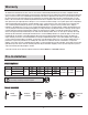
Pre-Installation (continued) PACKAGE CONTENTS A B C D E F G J H K I L N M Part Description Quantity Part Description Quantity A Mounting bracket (preassembled) 1 H Fan motor assembly 1 B Stop Valve (preassembled) 1 I Blade arm 8 C Neck of the mounting bracket (preassembled) 1 J Blade 8 D Canopy 1 K Light kit mounting plate 1 E Canopy bottom cover (preassembled) 1 L 18 watt LED Light kit 1 F Hanger ball/downrod assembly 1 M Glass shade 1 G Coupling cover 1
Installation MOUNTING OPTIONS NOTE: You may need a longer downrod to maintain proper blade clearance when installing on a steep, sloped ceiling. The maximum angle allowable is 18° away from horizontal. If the canopy (D) touches the hanger ball/downrod assembly (F), then remove the decorative canopy bottom cover (E), turn the canopy (D) 180° before attaching the canopy (D) to the mounting bracket (A).
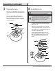
Assembly 1 2 Preparing the canopy Preparing the mounting bracket □ Remove the canopy bottom cover (E) from the canopy (D) by turning the canopy bottom cover (E) counterclockwise. □ Unscrew the four neck of the mounting bracket screws (CC) on the mounting bracket (A) to apart the mounting plate and neck of the mounting bracket (mounting neck) (C).
Assembly (continued) 3 4 Preparing the motor Assembling the fan □ Remove the cotter pin (HH) and clevis pin (GG), and loosen the two collar setscrews (LL) from the motor collar. WARNING: Failure to properly install the cotter pin (HH) could result in the fan loosening and possibly falling. □ Take out the setscrew #1 (JJ) and loosen the setscrew #2 (KK) located in the hanger ball (QQ), lower the hanger ball and remove the cross pin (II).
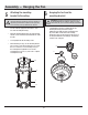
Assembly — Hanging the Fan 5 6 Attaching the mounting bracket to the ceiling WARNING: To reduce the risk of fire, electric shock or other personal injury, mount the fan only to an outlet box or supporting system marked acceptable for fan support and use the mounting screws provided with the outlet box. □ Pass the 120-volt supply wires through the center hole in the mounting bracket (A).
Assembly — Hanging the Fan (continued) 7 □ □ Installing the safety cable and the stop valve Secure the safety cable (SS) to the building structure using a wood screw (not included). A SS Secure the stop valve (B) onto mounting bracket (A) by tightening two stop valve screws (DD) to close up the opening of mounting bracket (A). DD 11 B HOMEDEPOT.COM/HOMEDECORATORS Please contact 1-800-986-3460 for further assistance.
Assembly — Hanging the Fan (continued) 8 Making the electrical connections WARNING: To avoid possible electrical shock, be sure electricity is turned off at the main fuse box before wiring. WARNING: Check to see that all connections are tight, including ground, and that no bare wire is visible at the wire nuts (except for the ground wire). Hot Neutral Black White Ground conductor PP CAUTION: To reduce the risk of electric shock, this fan must be installed with an isolating wall control/switch.
Assembly — Hanging the Fan (continued) 9 10 Installing the canopy NOTE: Adjust the canopy mounting screws (BB) as necessary until the canopy (D) and canopy bottom cover (E) are snug. WARNING: Make sure the tab on the mounting bracket (A) properly sits in the groove in the hanger ball/downrod assembly (F) before attaching the canopy (D) to the mounting bracket (A) by turning the canopy housing until it drops into place.
Assembly — Attaching the Fan Blades 11 Attaching the blades to the blade arms □ Attach the blades (J) to the blade arms (I) using the three blade attachment screws and fiber washers (EE). Start a screw and fiber washer (EE) into the blade arms (I), but do not tighten. □ Repeat for the two remaining blade attachment screws and fiber washers (EE). □ Tighten each screw securely starting with the center screw. Make sure the blade (J) is straight.
Assembly — Installing the Light Kit 13 Attaching the light kit mounting plate to the mounting ring □ Remove one of the three light kit mounting plate screws (MM) from the mounting ring (UU) and loosen the other two screws. (Do not remove.) □ Place the key holes in the light kit mounting plate (K) over the two screws (MM) previously loosened from the mounting ring (UU). Turn the light kit mounting plate (K) until the light kit mounting plate (K) locks in place at the narrow section of the key holes.
Operation PREPARING THE TRANSMITTER NOTE: Batteries will weaken with age and should be replaced before leaking takes place as this will damage the remote control. Dispose of used batteries properly and keep them out of the reach of children. N □ Remove the battery cover by pressing firmly on the arrow and sliding the cover off. □ Install two 1.5V AAA batteries (OO) (included). OO □ Replace the battery cover on the remote control (N).
Operation (continued) To clear all other remotes from your fan’s memory, use the steps below: □ Ensure AC power to the fan is OFF to begin the learning process. □ Slide the dip switch in the battery compartment to the "0" position. □ Turn the fan’s AC power ON. □ Within 60 seconds of turning AC power ON, press and release the “Pairing” button located in the remote’s battery compartment, and your fan will restore to the original setting and dismiss the other remotes.
Operation (continued) OPERATING YOUR FAN AND REMOTE CONTROL NOTE: The fan will store the last used speed setting for the next time it is turned on. NOTE: You must turn the fan on prior to using the speed or time functions. NOTE: On each start up of your ceiling fan, the fan blades will oscillate back and forth. This is a NORMAL OPERATION for DC motor ceiling fans as they go through a calibration cycle. The fan is NOT DEFECTIVE. 1. Fan button. - Press and release the button to turn the fan on or off.
Operation (continued) 4. Timer □ Pressing the timer buttons will automatically turn fan and light (if light is on) off after 2, 4, or 8 hours. When you activate the timer mode, the LED to the left of the time above the clock will illuminate. Off 2H 4H 8H Disables timer 5. Fan reverse button (Must be pushed when the fan is in operation) □ Warm weather: □ Cool weather: LED bar will illuminate and the lights will flow from high to low. LED bar will illuminate and the lights will flow from low to high.
Care and Cleaning Do □ Do not Check the support connections, brackets, and blade attachments twice a year. Make sure they are secure. Because of the fan’s natural movement, some connections may become loose over time. It is not necessary to remove the fan from the ceiling. □ Clean your fan periodically. Use only a soft brush or lint-free cloth to avoid scratching the finish. The plating is sealed with a lacquer to minimize discoloration or tarnishing.
Troubleshooting (continued) Problem The remote control is not working. Solution □ Do not connect the fan with wall mounted variable speed control(s). □ Make sure the frequency switches are set correctly. □ Reset the transmitter by going through the transmitter “LEARNING PROCESS”. □ Verify that all blades and blade bracket screws are secure (most fan wobble problems are caused by loose parts). Once the fan is properly installed, run the ceiling fan for 10 minutes to let the fan self-adjust.
Service Parts A B C AA J HH II BB D CC E DD K JJ KK LL F G H EE L MM FF NN GG OO M N I Part Description Part Description A Mounting bracket (preassembled) AA Plastic wire nut B Stop Valve (preassembled) BB Canopy mounting screw (preassembled) C Neck of the mounting bracket (preassembled) CC Neck of the mounting bracket screw (preassembled) D Canopy DD Stop valve screw (preassembled) E Canopy bottom cover (preassembled) EE Blade attachment screw and fiber washer F H
Questions, problems, missing parts? Before returning to the store, call Home Decorators Collection Customer Service 8 a.m. - 7 p.m., EST, Monday-Friday, 9 a.m. - 6 p.m., EST Saturday 1-800-986-3460 HOMEDEPOT.COM/HOMEDECORATORS Retain this manual for future use.