
Technical manual


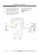


Table Of Contents
- ZW180_TO4GD-E-00
- INTRODUCTION
- SECTION AND GROUP CONTENTS
- SECTION 1 GENERAL
- SECTION 2 SYSTEM
- Group 1 Control System
- Group 2 ECM System
- Group 3 Hydraulic System
- Group 4 Electrical System
- Outline
- Main Circuit
- Electric Power Circuit
- Indicator Light Check Circuit
- Accessory Circuit
- Preheat Circuit
- Starting Circuit
- Charging Circuit
- Serge Voltage Prevention Circuit
- Engine Stop Circuit
- Lamplight Circuit
- Head Light Circuit
- Turn Signal Circuit
- Brake Light Circuit
- Hazard Light Circuit
- Horn Circuit
- Reverse Light/Buzzer Circuit
- Parking Brake Circuit
- Emergency Steering Check Circuit (Optional)
- SECTION 3 COMPONENT OPERATION
- Group 1 Pump Device
- Group 2 Control Valve
- Group 3 Hydraulic Fan Motor
- Group 4 Steering Pilot Valve
- Group 5 Steering Valve
- Group 6 Pilot Valve
- Outline (Standard Lever Type Pilot Valve for Front Attachment)
- Operation
- Electromagnetic Detent
- Outline (Joystick Type Pilot Valve for Front Attachment)
- Operation
- Electromagnetic Detent
- Outline (Two-Derectional Lever Type Pilot Valve for Additional Circuit) (Optional)
- Operation
- Outline (Joystick Type Pilot Valve for Additional Circuit) (Optional)
- Operation
- Group 7 Charging Block
- Group 8 Ride Control Valve
- Group 9 Drive Unit
- Group 10 Axle
- Group 11 Brake Valve
- Group 12 Others
- SERVICE MANUAL REVISION REQUEST FORM

SYSTEM / Control System
T2-1-48
Reverse Traveling Alarm Control
(Refer to the SYSTEM/Electric System group.)
Purpose: To sound the alarm buzzer when reverse of
the FNR lever or the FNR switch is selected.
Operation:
1. When reverse of the FNR lever or the FNR switch
is selected, MC grounds the terminal from the
reverse light relay.
2. The reverse light relay is excited, and current
flows to the reverse light and the reverse buzzer.
T4GD-02-01-004
MC ECM
Monitor
Unit
F
N
R
FNR Lever
or
FNR Switch
Reverse Buzzer
Right
Reverse Light
Left
Reverse Light
Reverse Light
Relay
From #11 of
Fuse Box A
From #8 o
f
Fuse Box A