
Technical manual


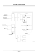


Table Of Contents
- ZW180_TO4GD-E-00
- INTRODUCTION
- SECTION AND GROUP CONTENTS
- SECTION 1 GENERAL
- SECTION 2 SYSTEM
- Group 1 Control System
- Group 2 ECM System
- Group 3 Hydraulic System
- Group 4 Electrical System
- Outline
- Main Circuit
- Electric Power Circuit
- Indicator Light Check Circuit
- Accessory Circuit
- Preheat Circuit
- Starting Circuit
- Charging Circuit
- Serge Voltage Prevention Circuit
- Engine Stop Circuit
- Lamplight Circuit
- Head Light Circuit
- Turn Signal Circuit
- Brake Light Circuit
- Hazard Light Circuit
- Horn Circuit
- Reverse Light/Buzzer Circuit
- Parking Brake Circuit
- Emergency Steering Check Circuit (Optional)
- SECTION 3 COMPONENT OPERATION
- Group 1 Pump Device
- Group 2 Control Valve
- Group 3 Hydraulic Fan Motor
- Group 4 Steering Pilot Valve
- Group 5 Steering Valve
- Group 6 Pilot Valve
- Outline (Standard Lever Type Pilot Valve for Front Attachment)
- Operation
- Electromagnetic Detent
- Outline (Joystick Type Pilot Valve for Front Attachment)
- Operation
- Electromagnetic Detent
- Outline (Two-Derectional Lever Type Pilot Valve for Additional Circuit) (Optional)
- Operation
- Outline (Joystick Type Pilot Valve for Additional Circuit) (Optional)
- Operation
- Group 7 Charging Block
- Group 8 Ride Control Valve
- Group 9 Drive Unit
- Group 10 Axle
- Group 11 Brake Valve
- Group 12 Others
- SERVICE MANUAL REVISION REQUEST FORM

SYSTEM / Control System
T2-1-7
Engine Control System Layout
T4GC-02-01-002
Work Mode
Selector Switch
L
N
P
A
ccelerator Pedal Sensor
A
ccelerator Pedal
Torque Converter Input
Speed Sensor
Transmission
Engine
Shift Switch
MC ECM
Monitor
Unit
Engine Coolant
Temperature Senso
r
Hydraulic Oil
Temperature
Sensor
Main Pump Delivery
Pressure Sensor
Torque Converter Output
Speed Sensor