
Workshop Manual


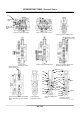

Table Of Contents
- COVER
- INTRODUCTION
- SAFETY
- CONTENTS
- SECTION 1 GENERAL
- SECTION 2 UPPERSTRUCTURE
- Cab
- Counterweight
- Main Frame
- Pump Device
- REMOVE AND INSTALL PUMP DEVICE
- DISASSEMBLE PUMP DEVICE
- ASSEMBLE PUMP DEVICE
- MAINTENANCE STANDARD
- ALLOWABLE LIMITS FOR CYLINDER BLOCK
- DISASSEMBLE REGULATOR
- ASSEMBLE REGULATOR
- DISASSEMBLE FAN PUMP
- ASSEMBLE FAN PUMP
- MAINTENANCE STANDARD
- DISASSEMBLE REGULATOR (FAN PUMP)
- ASSEMBLE REGULATOR (FAN PUMP)
- STRUCTURE OF PILOT PUMP
- Control Valve
- REMOVE AND INSTALL CONTROL VALVE
- DISASSEMBLE CONTROL VALVE (4-SPOOL HOUSING SIDE)
- ASSEMBLE CONTROL VALVE (4-SPOOL HOUSING SIDE)
- DISASSEMBLE CONTROL VALVE (5-SPOOL HOUSING SIDE)
- ASSEMBLE CONTROL VALVE (5-SPOOL HOUSING SIDE)
- DISASSEMBLE CONTROL VALVE (4-SPOOL HOUSING UPPER AND LOWER SURFACES)
- ASSEMBLE CONTROL VALVE (4-SPOOL HOUSING UPPER AND LOWER SURFACES)
- DISASSEMBLE CONTROL VALVE (5-SPOOL HOUSING UPPER AND LOWER SURFACES)
- ASSEMBLE CONTROL VALVE (5-SPOOL HOUSING UPPER AND LOWER SURFACES)
- DISASSEMBLE CONTROL VALVE (4-SPOOL CONTROL VALVE)
- ASSEMBLE CONTROL VALVE (4-SPOOL CONTROL VALVE)
- DISASSEMBLE CONTROL VALVE (5-SPOOL CONTROL VALVE)
- ASSEMBLE CONTROL VALVE (5-SPOOL CONTROL VALVE)
- DISASSEMBLE CONTROL VALVE (HOUSING FRONT AND REAR SURFACES)
- ASSEMBLE CONTROL VALVE (HOUSING FRONT AND REAR SURFACES)
- DISASSEMBLE HOUSING
- ASSEMBLE HOUSING
- Swing Device
- Pilot Valve
- Pilot Shut-Off Solenoid Valve
- Solenoid Valve
- Signal Control Valve
- Shockless Valve
- Fan Valve
- Fan Motor
- Engine
- SECTION 3 UNDERCARRIAGE
- SECTION 4 FRONT ATTACHMENT
- SERVICE MANUAL REVISION REQUEST FORM

UPPERSTRUCTURE / Control Valve
W2-5-31
• Disassemble Check Valve-2
14. Remove cap (60), check valve (37) and spring
(36) from housing (1).
: 14 mm
• Disassemble Main Relief Valve
IMPORTANT: Do not disassemble the main relief
valve. When the main relief valve is
disassembled, pressure must be
adjusted.
15. Remove the cap (46) assembly (38 to 55) from
housing (1).
: 41mm
IMPORTANT: As pilot seat (50) is installed to cap
(46), do not disassemble pilot seat
(50).
16. Remove sleeve (55) from cap (46) . Remove
spring (53) and main poppet (54) from sleeve
(55).
IMPORTANT: Put the matching marks on adjusting
screw (38), lock nut (40) and sleeve
(42). Record the rotation number of
adjusting screw (38).
17. Loosen lock nut (40). Remove adjusting screw
(38) from sleeve (42). Remove piston (41), spring
(48) and poppet (49) from sleeve (42).
: 30 mm, 22 mm
IMPORTANT: Put the matching marks on sleeve
(42), lock nut (45) and cap (46).
Record the rotation number of
sleeve (42).
18. Loosen lock nut (45). Remove sleeve (42) from
cap (46).
: 41 mm
• Disassemble Flow Combiner Valve
19. Remove cap (64), spring (63), spacer (62) and
spool (61) from housing (1).
: 46 mm