
Operation Manual


10
English
ASSEMBLY PROCEDURES
Drive shaft to engine (Fig. 1)
Loosen tube locking bolt (1) about ten turns so that the bolt point will
not obstruct drive shaft tube to be inserted. When inserting drive
shaft tube, hold the tube locking bolt outward preventing inside
fi tting from obstructing as well.
Insert the drive shaft into the clutch case of the engine properly until
the marked position (2) on the drive shaft tube meets the clutch
case.
Some models may come with the drive shaft already installed.
NOTE
When it is hard to insert drive shaft up to the marked position on
the drive shaft tube, turn drive shaft by the cutter mounting end
clockwise or counter-clockwise. Tighten tube locking bolt lining
up the hole in the shaft tube. Then tighten clamp bolt securely.
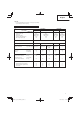
Model
TCG27EBSP TCG27EBDP
(SL) (S) (SL) (SLN)
Engine
Displacement (cm
3
)
Spark plug
Idling speed (min
-1
)
Speed of output shaft (min
-1
)
Max. engine output (kW)
26.9
NGK BMR7A
2800 – 3200
7600
0.9
26.9
NGK BMR7A
2800 – 3200
7600
0.9
26.9
NGK BMR7A
2800 – 3200
7600
0.9
26.9
NGK BMR7A
2800 – 3200
7600
0.9
Fuel tank capacity (cm
3
)520
Dry weight (kg) 5.2 5.4 5.4 4.5
Cutting attachment Type / Dia. (mm) Nylon cord Nylon cord
Metal blade
(255)
Nylon cord ------
Sound pressure
level LpA
(dB (A))
(ISO22868)
Equivalent*
Uncertainty
86
3
86
3
85
3
86
3
86
3
Measured sound
power level LwA (dB (A))
Guaranteed sound
power level LwA (dB (A))
(2000/14/EC)
Racing
(2000/14/EC)
Racing
108
111
108
111
108
111
108
111
------
------
Vibration level (m/s
2
) (ISO22867)
Equivalent (Front / Left handle)*
Equivalent (Rear / Right handle)*
Uncertainty
6.7
4.1
2.0
4.1
3.0
1.2
3.7
2.6
1.2
5.3
3.4
2.0
------
------
------
NOTE
Equivalent noise level/vibration level are calculated as the time-weighted energy total for noise/vibration levels under various working
conditions with the following time distribution:
* 1/2 Idle, 1/2 racing.
All data subject to change without notice.
Installation of attachment
1. Join the attachment in place of it.
2. Make sure the lock pin (3) fi ts in the location hole (4) of tube and
that the tube will not come off . (Fig. 2)
3. Tighten the knob nut (5) securely. (Fig. 2)
Installation of handle
WARNING
Always use a barrier bar (6) and shoulder harness with the loop
handle. (Fig. 3)
Attach the handle to the drive shaft tube with the angle towards the
engine.
Adjust the location to the most comfortable position before
operation.
NOTE
If your unit has handle location label on drive shaft tube, follow
the illustration.
000Book_TCG24EBSP_WE.indb 10000Book_TCG24EBSP_WE.indb 10 2014/03/26 14:05:122014/03/26 14:05:12