
User's Manual


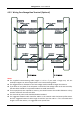

Table Of Contents
- Chapter 1 Overview
- Chapter 2 Installation
- Chapter 3 Disassembling before Maintenance
- Chapter 4 Wiring
- 4.1 Components Introduction
- 4.2 Wiring Electric Supply
- 4.3 Wiring Interconnecting Cable
- 4.4 Terminal Description
- 4.4.3 Master Control Board Terminal Description
- 4.4.4 Slave Control Board Terminal Description
- 4.4.5 Main Control Board Terminal Description
- 4.4.6 Main Control Board Serial Port ID Description
- 4.4.7 RS-485 Wiring
- 4.4.8 RS-232 Wiring
- 4.4.9 Wiegand Wiring
- 4.4.10 Barrier Control Wiring
- 4.4.11 Alarm Output Wiring
- 4.5 Wiring Lithium Battery (Optional)
- Chapter 5 Device Settings
- Chapter 6 Device Activation
- Chapter 7 Client Operation
- 7.1 Function Module
- 7.2 Access Control Management
- 7.2.1 Adding Access Control Device
- 7.2.2 Viewing Device Status
- 7.2.3 Editing Basic Information
- 7.2.4 RS-485 Settings
- 7.2.5 Authenticating M1 Card Encryption
- 7.2.6 Remote Configuration
- Checking Device Information
- Editing Device Name
- Editing Time
- Setting System Maintenance
- Setting RS-485 Parameters
- Managing Network User
- Managing Remote Control User
- Setting Security
- Configuring Passing Parameters
- Configuring Screen Parameters
- Configuring People Counting Parameters
- Configuring Network Parameters
- Configuring Advanced Network
- Configuring Relay Parameters
- Configuring Audio File
- Operating Relay
- Viewing Relay Status
- 7.3 Organization Management
- 7.4 Person Management
- 7.5 Permission Configuration
- 7.6 Advanced Functions
- 7.7 Searching Access Control Event
- 7.8 Access Control Event Configuration
- 7.9 Door Status Management
- 7.10 Arming Control
- 7.11 Time and Attendance
- Appendix A Tips for Scanning Fingerprint
- Appendix B DIP Switch Description
- Appendix C Table of Audio Index Related Content

Swing Barrier·User Manual
20
4.3.2 Wiring Face Recognition Terminal (Optional)
Notes:
The supplied interconnecting cable length is 3.75 m. If you need a longer one, ask our
technique supports or sales and purchase 5.5 m interconnecting cables.
The suggested inner diameters of the low voltage conduit should be larger than 30 mm.
If you want to bury both of the AC power cord and the low voltage cable at the entrance side,
the two cables should be in separated conduits to avoid interference.
If more peripherals are required to connect, you should increase the conduit diameter or bury
another conduit for the external cable.
The external AC power cord should be double-insulated.
The suggested network cable should be CAT5e or the network cable has better performance.
And the suggested network cable length should be less than 100 m. If the communication
length is more than 100 m, it is suggested to use optical fiber.