
User's Manual


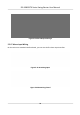

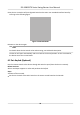


Table Of Contents
- Legal Information
- Regulatory Information
- Safety Instruction
- Available Models
- Chapter 1 Overview
- Chapter 2 Light Introduction
- Chapter 3 System Wiring
- Chapter 4 Installation
- Chapter 5 General Wiring
- 5.1 Components Introduction
- 5.2 Wiring
- 5.3 Terminal Description
- 5.3.1 Main Lane Control Board Terminal Description
- 5.3.2 Sub Lane Control Board Terminal Description
- 5.3.3 Main Access Control Board Terminal Description
- 5.3.4 Sub Access Control Board Terminal Description
- 5.3.5 Main User Extended Interface Board
- 5.3.6 Sub User Extended Interface Board
- 5.3.7 User Core Board Terminal Description
- 5.3.8 Card Reader Board Terminal Description
- 5.3.9 Arrow Light Board Terminal Description
- 5.3.10 Upper IR Detector Board Terminal Description
- 5.3.11 Lower IR Detector Board Terminal Description
- 5.3.12 RS-485 Wiring
- 5.3.13 RS-232 Wiring
- 5.3.14 Wiegand Wiring
- 5.3.15 Barrier Control Wiring
- 5.3.16 Alarm Output Wiring
- 5.3.17 Alarm Input Wiring
- Chapter 6 Device Settings
- Chapter 7 Activation
- Chapter 8 Operation via Web Browser
- 8.1 Login
- 8.2 Overview
- 8.3 Person Management
- 8.4 Search Event
- 8.5 Device Management
- 8.6 Configuration
- 8.6.1 View Device Information
- 8.6.2 Set Time
- 8.6.3 Set DST
- 8.6.4 Change Administrator's Password
- 8.6.5 Online Users
- 8.6.6 View Device Arming/Disarming Information
- 8.6.7 Network Settings
- 8.6.8 Set Video and Audio Parameters
- 8.6.9 Set Image Parameters
- 8.6.10 Event Linkage
- 8.6.11 Access Control Settings
- 8.6.12 Turnstile
- 8.6.13 Card Settings
- 8.6.14 Set Privacy Parameters
- 8.6.15 Set Biometric Parameters
- 8.6.16 Set Screen Display
- 8.6.17 Notice Publication
- 8.6.18 Prompt Schedule
- 8.6.19 Upgrade and Maintenance
- 8.6.20 Device Debugging
- 8.6.21 Component Status
- 8.6.22 Log Query
- 8.6.23 Certificate Management
- Chapter 9 Configure the Device via the Mobile Browser
- 9.1 Login
- 9.2 Overview
- 9.3 Configuration
- Chapter 10 Client Software Configuration
- 10.1 Configuration Flow of Client Software
- 10.2 Device Management
- 10.3 Group Management
- 10.4 Person Management
- 10.5 Configure Schedule and Template
- 10.6 Set Access Group to Assign Access Authorization to Persons
- 10.7 Configure Advanced Functions
- 10.8 Door/Elevator Control
- Appendix A. Tips When Collecting/Comparing Face Picture
- Appendix B. DIP Switch
- Appendix C. Event and Alarm Type
- Appendix D. Error Code Description
- Appendix E. Communication Matrix and Device Command

5.3.11 Lower IR Detector Board Terminal Descripon
Figure 5-14 Lower IR Detector Board
5.3.12 RS-485 Wiring
The main and sub user extended interface board each has one RS-485 interface.
Note
●
If
connecng the RS-485 with a card reader, by default, the DIP switch of the card reader is: 1 for
entrance, and 4 for exit.
●
If there are other RS-485 devices connecng, the ID of the RS-485 cannot be conicted.
●
The connected 12 V power interface for the face recognion terminal cannot be connected with
other 12 V devices.
Figure 5-15 RS-485 Wiring
DS-K3B631TX Series Swing Barrier User Manual
28