
Quick Start Guide


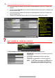


R E A R P A N E L
No.
Item
Description
1
Audio In
RCA connectors
for audio input
2
Audio Out
RCA connectors for audio output
3
Line In
Mic input for two
-
way communication
4
HDMI
2
HDMI video output connector
5
RS
-
232 Interface
Connector for RS
-
232 devices
6
eSATA
Connector to external eSATA drive
7
LAN
2
Connector
for LAN (Local Area Network)
8 RS-485
Connector for RS
-
485 devices: T+ and T
-
pins connect to R+ and R
-
pins of PTZ
receiver respectively
D+, D
-
pin connects to Ta, Tb pin of controller (for cascading devices, the first DVR’s
D+, D
-
pin should be
connected with the D+, D
-
pin of the next DVR)
9
KB
Connector for keyboard
1
0
Alarm
Out
Connector for alarm out
put
s
1
1
Power Switch
Switch for turning device on/off
12
Power Input
100 to 240 VAC
power
1
3
Video In
BNC connectors for video input
1
4
USB
Interface
Connect to USB mouse or USB flash memory devices
1
5
Video Out
BNC connector for video output
1
6
HDMI
1
HDMI video output connector
1
7
VGA
DB
-
15 connector for VGA output to display local video output and menu
18
LAN
1
Connector for LAN (Local
Area Network)
19
Alarm In
Connectors for alarm inputs
20
Ground
Connect before powering up
1 C O N N E C T D E V I C E S
1. Connect power supply to the DVR.
2. Connect DVR to LAN using Cat 5e cable.
3. Connect video monitor(s) to DVR using HDMI and/or VGA cables, as appropriate.
4. Connect mouse to USB port (wireless mouse can be used in lieu of included mouse).
5. Connect to audio I/O using RCA connectors.
2 S T A R T T H E D V R
1. Plug power supply plug into 110 to 240 VAC outlet (surge suppressor is recommended).
2. Turn power switch on. Power indicator LED will turn green to indicate unit is starting.
3. After startup, power indicator LED will remain green.