
User Manual


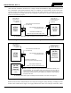


Table Of Contents
- 1 REGULATORY AND SAFETY INFORMATION
- 1.1 SAFETY SYMBOL CONVENTIONS
- 1.2 RF ENERGY EXPOSURE AWARENESS AND CONTROL INFORMATION FOR FCC OCCUPATIONAL USE REQUIREMENTS
- 1.3 COMPLIANCE WITH RF EXPOSURE STANDARDS
- OCCUPATIONAL SAFETY GUIDELINES AND SAFETY TRAINING INFORMATION
- 1.5 COMMON HAZARDS
- 1.6 SAFE DRIVING RECOMMENDATIONS
- 1.7 OPERATING RULES AND REGULATIONS
- 1.8 OPERATING TIPS
- 2 SPECIFICATIONS
- 3 INTRODUCTION
- 4 UNPACKING AND CHECKING THE EQUIPMENT
- 5 PLANNING THE INSTALLATION
- 6 ANTENNA INSTALLATION
- 6.1 ANTENNA MOUNTING LOCATIONS
- 6.2 ANTENNA INSTALLATION PROCEDURES
- 6.2.1 Installing NMO Antenna Mounts AN125001-001, 002, 003 and 004
- 6.2.2 Installing NMO Magnetic Antenna Mounts AN125001-007 and AN125001-008
- 6.2.3 Installing All Other Antenna Mounts
- 6.2.4 Attaching NMO Antenna Elements
- 6.2.5 Installing the Coax Cable and TNC RF Connector
- 6.2.6 Install GPS Antenna (Required Only if Radio has GPS Receiver Option)
- 7 FRONT-MOUNT RADIO INSTALLATION
- 8 REMOTE-MOUNT RADIO INSTALLATION
- 8.1 MOUNTING THE REMOTE-MOUNT RADIO
- 8.2 REMOTE-MOUNT RADIO’S DC POWER INSTALLATION
- 8.3 CH721 CONTROL HEAD INSTALLATION
- 8.4 HHC731 HAND-HELD CONTROLLER INSTALLATION
- 9 SPEAKER INSTALLATION
- 10 MICROPHONE ATTACHMENT
- 11 OPTIONAL CABLES
- 12 GPS NMEA-FORMATTED SERIAL DATA CONNECTION
- 13 INITIAL POWER-UP TEST
- 14 PERFORMANCE TESTS
- 15 COMPLETE THE INSTALLATION
- 16 WARRANTY REGISTRATION
- 17 WARRANTY

MM-014763-001, Rev. G
75
(Other controls are same as shown for Scan model.)
Figure 8-6: CH-721 System Model Control Head Front Panel
The CH-721 control heads feature a large easy-to-read 3-line graphical vacuum fluorescent display, an
on/off/volume control knob, menu controls and buttons, trunking mode buttons, an emergency/home
button, a scan on/off button, and three (3) preset buttons. Other front panel components include a
microphone connector and LED-type indicators. One LED indicator is the busy indicator that lights when
the radio is receiving a call and one is the transmitter-enabled indicator that lights when the radio is
transmitting. The front panel also has an ambient light sensor for automatic display dimming.
Figure 8-7: CH-721 Rear Panel (both control head models)
Prior to installing the control head, verify it has the proper software version installed and
verify it has been properly configured for customer use.
Because Installation Kit MAMW-NZN7R contains the most complete set of materials for
installing the radio and control head, the following instructions make repeated reference
to items within this kit. Item numbers given in parenthesis refer to items in the kit as
listed in Table 4-5 on page 30.
NOTE
NOTE
12-Button Keypad
Clear Button
Menu Button
Option Button
CAN Port
Connectors
(2 places)
Speaker Audio
Connector
Serial Port Connector
(DB-9)
DC Power
Connector
Accessory Connector
(DB-25)
Note: Serial and Accessory connectors are
shown without waterproof covers.