
User Manual

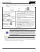


Table Of Contents
- 1 REGULATORY AND SAFETY INFORMATION
- 1.1 SAFETY SYMBOL CONVENTIONS
- 1.2 RF ENERGY EXPOSURE AWARENESS AND CONTROL INFORMATION FOR FCC OCCUPATIONAL USE REQUIREMENTS
- 1.3 COMPLIANCE WITH RF EXPOSURE STANDARDS
- OCCUPATIONAL SAFETY GUIDELINES AND SAFETY TRAINING INFORMATION
- 1.5 COMMON HAZARDS
- 1.6 SAFE DRIVING RECOMMENDATIONS
- 1.7 OPERATING RULES AND REGULATIONS
- 1.8 OPERATING TIPS
- 2 SPECIFICATIONS
- 3 INTRODUCTION
- 4 UNPACKING AND CHECKING THE EQUIPMENT
- 5 PLANNING THE INSTALLATION
- 6 ANTENNA INSTALLATION
- 6.1 ANTENNA MOUNTING LOCATIONS
- 6.2 ANTENNA INSTALLATION PROCEDURES
- 6.2.1 Installing NMO Antenna Mounts AN125001-001, 002, 003 and 004
- 6.2.2 Installing NMO Magnetic Antenna Mounts AN125001-007 and AN125001-008
- 6.2.3 Installing All Other Antenna Mounts
- 6.2.4 Attaching NMO Antenna Elements
- 6.2.5 Installing the Coax Cable and TNC RF Connector
- 6.2.6 Install GPS Antenna (Required Only if Radio has GPS Receiver Option)
- 7 FRONT-MOUNT RADIO INSTALLATION
- 8 REMOTE-MOUNT RADIO INSTALLATION
- 8.1 MOUNTING THE REMOTE-MOUNT RADIO
- 8.2 REMOTE-MOUNT RADIO’S DC POWER INSTALLATION
- 8.3 CH721 CONTROL HEAD INSTALLATION
- 8.4 HHC731 HAND-HELD CONTROLLER INSTALLATION
- 9 SPEAKER INSTALLATION
- 10 MICROPHONE ATTACHMENT
- 11 OPTIONAL CABLES
- 12 GPS NMEA-FORMATTED SERIAL DATA CONNECTION
- 13 INITIAL POWER-UP TEST
- 14 PERFORMANCE TESTS
- 15 COMPLETE THE INSTALLATION
- 16 WARRANTY REGISTRATION
- 17 WARRANTY

MM-014763-001, Rev. G
52
damage, dirt, and/or metal shavings which may be generated during the mechanical and electrical
installation of the radio. Temporarily tying the connector and cable-end within a small plastic bag is
recommended.
Actual Size; Dimensions are in Inches
(VS-AN-025167-010 Rev. A)
Figure 6-7: Crimping Instructions for TNC RF Connector
If the mobile radio installation includes a unity-gain antenna
part number
AN102800V1 or AN102800V2, the antenna element must be tuned (trimmed) for
maximum performance (i.e., minimum reflection) during the test procedures presented
in Section 14. Other antennas used with the M5300 are factory-tuned and therefore do
not require tuning in the field.
6.2.6 Install GPS Antenna (Required Only if Radio has GPS Receiver Option)
If the M7300 radio is equipped with the GPS receiver option, the GPS receiver requires connection to an
externally-mounted GPS antenna. The GPS antenna must be kept at least six (6) inches away from any
other antenna mounted on the vehicle and it must have at least six inches of surface ground plane beneath
it. The following antenna installation procedure is recommended:
NOTE
1. Before cutting the cable to a shorter length, refer to the previous
WARNING. Some antenna cables should never to cut, while others
can be cut to as short as 6 feet.
2. Trim the end of the cable to the dimensions shown at the left, taking
care not to nick the cable’s inner conductor or its braid/shield.
3. Slip the crimp sleeve over the end of the cable, with its flanged-end
facing towards the end of the cable.
4. Place the contact onto the cable’s inner conductor. The end of the
contact and the cable’s inner dielectric mu
st “butt square” together, as
shown to the left.
5.
While holding the contact tight against the dielectric, crimp the contact
to the inner conductor using an appropriate crimp tool.
6. Flair the cable’s outer braid/shield and then gently but firmly push the
con
tact (and cable end) into the connector housing until a gentle snap
is felt, indicating the contact is locked in place.
7. Slip the crimp sleeve in place, butting its flanged-end against the
connector housing.
8. Using an appropriate crimp tool, crimp the crimp sleeve securely to
the cable end and connector housing. When crimping, hold the
housing and sleeve firmly together, and to the cable end.