
User's Manual


MM102554V1 REV B
58
8. STATION TEST AND ALIGNMENT PROCEDURES
8.1 INTRODUCTION
This chapter provides instructions for testing and aligning the MASTR III Conventional or P25 Base
Station. The base station is normally pre-aligned at the factory and ready to install. However, after initial
installation and prior to placing the equipment into operation, it should be rechecked to ensure it is
operating properly and meets the required specifications.
These procedures assume the receiver and transmitter modules have been previously tuned and aligned
and should be used whenever a module or system component is repaired or replaced.
8.2 GENERAL
The MASTR III ADC Base Station comes pre-programmed and ready to install, the only adjustments
needed are the required Line Output Level, the Line Input Level necessary to produce Standard
Deviation, and the Line Cancellation for 2-wire Tone Remote Orientation. These adjustments can be
made using the PC Programming option TQS3353, the Utility PC software TQ0619, or with the Utility
Handset SPK9024.
The rated system deviations are as follows:
• 5.0 kHz Standard (25 kHz IF)
• 4.0 kHz NPSPAC
• 2.5 kHz Narrow (12.5 kHz narrowband)
• 2.8 kHz P25
8.3 SUPPORT EQUIPMENT REQUIRED
The following equipment and software may be require to perform the MASTR III ADC Base station
alignment and tests:
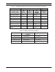
8.3.1 Hardware
Table 8-1: Hardware Requirements
DESCRIPTION MODEL NUMBER PURPOSE
Communication Test Set IFR 1200, 1500 or
equivalent
System test and alignment
Directional Coupler Narda 3020A or
equivalent
Test output power
RF Coaxial Load Resistor Bird 8235 Test and alignment
RF Power Meter with 3%
measurement accuracy
Boonton
4220A/51033er or
equivalent
Test output power
Attenuator, 10 dB, 100 W Bird 8343-100 Test and alignment